Various Devices of Refrigerator


Compressors
Positive-displacement compressors
- Examples: reciprocating compressor, rotary compressor, scroll compressor, screw compressor.
- The working fluid in a positive-displacement compressor undergoes non-flow (closed-boundary) processes during compression: the mass in the compression space is fixed while the boundary moves to change the volume.
- Work is transferred to the fluid through a hydrostatic force acting on the moving boundary (piston/rotor), not by momentum transfer of a high-speed stream.
- Positive-displacement machines normally incorporate valves or clearances that help prevent reversal of flow at the suction and discharge ports.
Non-positive (dynamic) compressors
- The fluid is subject to a flow process where compression occurs by the continuous action of vanes or blades moving at high speed (momentum change).
- Work is transferred by the change of momentum of the moving fluid as it passes over rotor blades; typical examples are centrifugal and axial compressors.
- Dynamic compressors do not inherently prevent reversal of flow when off-design conditions occur; flow control or guide vanes are commonly needed.
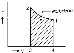
- Work done by the compressor on a p-v diagram for a particular dynamic machine is represented by the enclosed area (for some taught examples this is given as area 1-2-3-4).
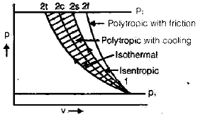
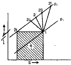
Various compression processes and specific work
Different thermodynamic compression processes give different amounts of work for the same pressure rise. Common idealised processes used for analysis are isentropic, isothermal and polytropic compression. The specific work required varies with the process; for example, isothermal compression requires the least work for an ideal gas between two pressures.
| Compression process | Work done |
|---|---|
| Isentropic compression | 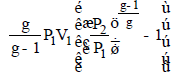 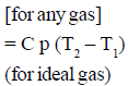 |
| Isothermal compression | 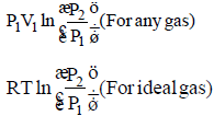 |
| Polytropic compression | 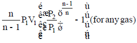 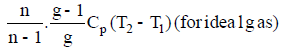 |
- For an ideal gas between the same inlet and outlet pressures, isothermal compression requires the least work among the common idealised processes.
Volumetric efficiency of a reciprocating compressor
Volumetric efficiency (ηv) is a measure of the effectiveness with which a reciprocating compressor inducts suction gas during the suction stroke compared with its geometric swept volume. It is important because it directly affects the mass flow rate and thus the refrigeration capacity of the system.
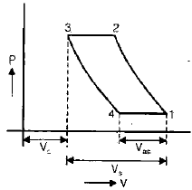
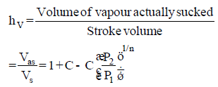
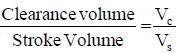
Clearance ratio (C) is the ratio of the clearance volume (volume remaining in the cylinder at the end of discharge stroke) to the swept volume. The clearance ratio expression is shown below.
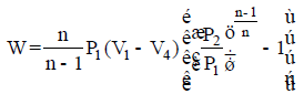
- When clearance volume is present, the effective mass inducted on the next suction is reduced; the work done and the net delivery change. The expression for work done with clearance is shown here:
- If suction pressure decreases or clearance volume increases, the volumetric efficiency decreases; consequently the refrigeration capacity and the system COP fall.
Hermetically sealed unit
- In a hermetically sealed unit the motor, compressor cylinder and crankcase are enclosed in a single sealed housing so the refrigerant and oil circulate within the enclosure.
- Advantages are no external leakage, lower noise and compactness - typical of many domestic refrigerators and small commercial units.
- Disadvantages: a separate pump or specialised service equipment is required for evacuation and refrigerant charge changes because the unit cannot be opened easily.
- A drier or moisture-absorbing device is often installed in the suction line during servicing to remove moisture and avoid moisture-induced choking or freezing in the expansion device.
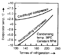
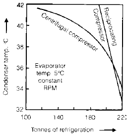
Reciprocating compressor vs centrifugal compressor
- Reciprocating compressors are suitable for applications requiring relatively low mass flow but high discharge pressures (high compression ratios per stage).
- Centrifugal compressors are suitable for applications requiring large mass flow rates with relatively low to moderate pressure rise per stage.
Condensers
- In a vapour-compression refrigeration cycle, heat is rejected to the surroundings in the condenser after the refrigerant has been compressed.
- The sensible heat (cooling of superheated vapour to saturated vapour, and further cooling of saturated liquid to subcooled liquid) is usually small compared with the latent heat released during condensation at constant temperature and pressure.
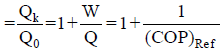
The rejected heat Qk from the condenser equals the refrigeration effect plus the compressor work:
Qk = Q0 + W
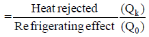
The heat rejection ratio (a comparative indicator) is often shown graphically or as a relation; an illustrative form is provided below.
Types of condensers
Air-cooled condenser
- Refrigerant flows inside the tubes while ambient air flows over the outside of the tubes to remove heat.
- These condensers are commonly used in domestic refrigerators, window air-conditioners and small capacity water coolers because they require no cooling water system.
Water-cooled condenser
- Cooling water flows inside tubes (tube-in-shell arrangements are common) while refrigerant condenses on the shell side in many designs.
- These condensers are used where a supply of cooling water and a cooling tower or once-through water source is available; they operate at lower condenser temperatures than air-cooled condensers.
Evaporative condenser
- An evaporative condenser combines condensation and evaporative cooling: refrigerant first rejects heat to circulating water; that water then gives up heat to air by evaporation (similar to a cooling tower).
- Evaporative condensers typically require a larger quantity of refrigerant and longer piping for the water circulation loop compared with direct water-cooled condensers.
- They are commonly used in large ammonia refrigeration plants and in industrial applications where evaporative cooling is acceptable.
- The thickness of the condensate film on tubes affects heat transfer: very long vertical tubes or very large horizontal tube diameters can lead to thicker condensate films and a lower heat transfer coefficient.
- Fins are usually provided on the air side of air-cooled parts because the air-side convective heat transfer coefficient is much lower than the refrigerant-side coefficient; adding fins increases the total heat transfer coefficient.
- Even a small quantity of air or non-condensable gases in the condenser severely reduces the effective heat transfer at the wall; therefore purge valves or evacuated lines are used to remove non-condensables.
- The main disadvantage of air-cooled condensers is that they operate at higher condenser temperatures (and hence higher compressor work) compared with water-cooled condensers under the same conditions.
- Cooling towers operate on the principle of evaporative cooling and are often paired with water-cooled condensers to reject heat to atmosphere.
- The capacity of a cooling tower increases as the wet-bulb temperature of the air decreases; lower wet-bulb gives more effective evaporative cooling.

Types of cooling towers
- Natural draft cooling towers - air flow is generated by buoyancy due to temperature differences (large hyperbolic towers). Common configurations include spray towers and splash (or baffle) type towers.
- Mechanical draft cooling towers - fans are used to move air; subtypes include forced-draft (fans push air into the tower) and induced-draft (fans draw air through the tower).
- Advantages of mechanical draft towers over natural draft towers:
- Smaller in size for the same duty.
- Cooling capacity can be controlled by varying the forced air flow (fan speed or blade pitch).
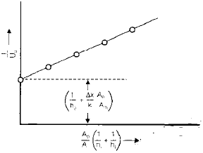
- This experimental arrangement (shown above) is used to determine the overall condensing coefficient under actual operating conditions for a given condenser design and operating point.
Expansion devices
- The expansion device reduces refrigerant pressure from the condenser pressure level to the evaporator pressure level.
- It supplies liquid refrigerant to the evaporator at the rate the refrigerant is evaporated in the evaporator, thereby controlling evaporator level and avoiding liquid carry-over to the compressor.
- The expansion process in these devices is essentially a throttling (isenthalpic) process - useful work is not produced or recovered during throttling.
Types of expansion devices
Variable restriction type
- Automatic expansion valve: maintains a near-constant degree of superheat at the evaporator outlet by varying the valve opening in response to evaporator pressure/temperature. Suitable for varying load conditions.
- Thermostatic expansion valve (TXV): senses evaporator outlet superheat and modulates refrigerant flow to keep that superheat approximately constant; widely used for refrigeration and air conditioning systems with varying loads.
- High-side float valve: maintains a constant liquid level in a receiver or condenser by controlling refrigerant flow on the high-pressure side.
- Low-side float valve: maintains a constant liquid level in the evaporator by controlling refrigerant inlet on the low-pressure side; common in flooded evaporator systems.
Constant restriction type
- Capillary tube: a fixed-geometry long thin tube that produces a pressure drop through viscous flow and friction. The pressure drop (and enthalpy drop) is roughly proportional to length and inversely proportional to the fourth power of the diameter (for laminar flow regimes) and depends on flow regime in practice.
- Capillary tubes are suitable for simple on-off control: the compressor starts and builds pressure until the required operating conditions are met; they are inexpensive and have no moving parts.
- Because they have no active compensation for varying loads or ambient conditions, capillary tubes are less flexible than thermostatic or automatic valves for systems with large load variations.
Evaporators
The evaporator absorbs heat from the medium to be cooled (air, water, or a process fluid) and evaporates the liquid refrigerant; it is the heat-absorbing element of a refrigeration system.
- Flooded evaporator: the refrigerant covers the entire heat transfer surface; a pool of liquid refrigerant is present and a float valve commonly controls the liquid level.
- In flooded evaporators the refrigerant often flows outside the tubes (shell-and-tube or plate-type arrangements), and pool boiling occurs on the heat transfer surface; these are common in large chillers.
- Dry (or dry-expansion) evaporator: refrigerant occupies only part of the heat transfer surface and some surface area is used to superheat the vapour before it leaves the evaporator; a TXV or capillary tube is used with dry evaporators.
- In dry evaporators the refrigerant usually flows inside the tubes and forced-convection boiling occurs; common in domestic refrigerators, ice-making plants and many air-conditioning evaporators.
- Dry evaporators may use horizontal tube coils (commonly used and can provide higher heat transfer coefficients for certain flow orientations) or vertical tube coils (sometimes used where space or drainage considerations favour vertical orientation and may have different heat transfer performance).
Practical notes and applications
- Choice of compressor type depends on required discharge pressure, mass flow rate and system economy: reciprocating for high pressure ratio and lower flow, centrifugal for high flow, moderate pressure rise.
- Selection of condenser type depends on available utilities: air-cooled where water is scarce; water-cooled with cooling tower where site allows; evaporative condensers for large industrial installations where evaporative cooling is economical.
- Expansion device selection depends on control requirements: TXV for variable loads and precise superheat control; capillary tube for small fixed-load systems due to simplicity and low cost.
- Proper removal of non-condensable gases and moisture, correct sizing of clearances and correct refrigerant charge are essential for reliable, efficient refrigeration plant operation.
Summary
This chapter described the various devices used in vapour-compression refrigeration systems: compressors (positive-displacement and dynamic), condensers (air-cooled, water-cooled, evaporative), expansion devices (variable and constant restriction types) and evaporators (flooded and dry). For each device the working principle, typical uses and practical considerations were discussed. The provided images and formula placeholders show standard diagrams and relations used in analysis of work, volumetric efficiency and heat rejection.
FAQs on Various Devices of Refrigerator
| 1. What are the different devices used in a refrigerator? |  |
| 2. How does the compressor in a refrigerator work? | |
| 3. What is the role of the condenser in a refrigerator? | |
| 4. How does the evaporator in a refrigerator work? | |
| 5. What is the function of the expansion valve in a refrigerator? | |


