First Law Applied to Flow Processes

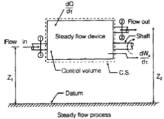
Steady Flow Process
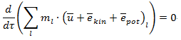
Steady flow means that at any fixed point in the flow field the fluid properties (pressure, temperature, velocity, density, etc.) do not change with time. In a steady flow process there is no accumulation of mass or energy within the chosen control volume; therefore mass and energy balances reduce to equality between inflow and outflow rates.
- No accumulation: mass flow entering the control volume equals mass flow leaving the control volume.
The common symbols and their units used in steady-flow energy discussions are listed below.
A1, A2 - cross-sectional area of stream (m2)
m1, m2 - mass flow rates entering and leaving the control volume (kg/s)
p1, p2 - absolute pressure (N/m2)
v1, v2 - specific volume (m3/kg), where specific volume v = 1/ρ
u1, u2 - specific internal energy (J/kg)
V1, V2 - flow velocities (m/s)
Z1, Z2 - elevations above a chosen datum (m)
Q̇ - net rate of heat transfer through the control surface (J/s)
Ẇ - net rate of work transfer through the control surface (J/s)
t - time (s)
Conservation of Mass for Steady Flow
For steady flow, mass conservation gives
ṁin = ṁout

For a single stream, mass flow rate ṁ can be written as
ṁ = ρ A V = (A V) / v
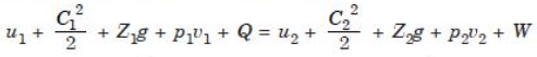
Conservation of Energy - Steady Flow Energy Equation (SFEE)
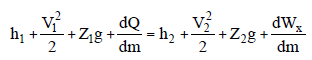
The first law (energy conservation) applied to a steady-flow control volume gives the steady-flow energy equation. In its most general per unit time form:
Q̇ - Ẇs = ṁ [ (h2 + V22/2 + g Z2) - (h1 + V12/2 + g Z1) ]
Divide by ṁ to express per unit mass (lower-case symbols denote specific or per-unit-mass quantities):
q - w = (h2 - h1) + (V22 - V12)/2 + g (Z2 - Z1)
where q is heat transfer per unit mass and w is shaft work done by the fluid per unit mass (positive when work is produced by the fluid). Sign convention must be stated clearly before using the equation.
In many engineering applications, some terms are negligible (small kinetic or potential energy change) and the equation simplifies accordingly.
- Per unit mass basis: useful when comparing specific changes in enthalpy, kinetic and potential energies.
- Per unit time basis: useful for energy rates (power) in systems with a single dominant stream.
- Application: steady-flow engineering devices such as nozzles, diffusers, turbines, compressors, throttling valves and heat exchangers.
Nozzles and Diffusers
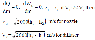
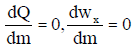
In both devices heat transfer and shaft work are usually negligible. The SFEE reduces to a balance between enthalpy and kinetic energy (and possibly potential energy):
h1 + V12/2 ≈ h2 + V22/2
- Nozzle: a device that accelerates the fluid so that velocity (kinetic energy) increases at the expense of pressure/enthalpy. Typical use: jets, steam nozzles.
- Diffuser: a device that decelerates the fluid so that pressure (or enthalpy) increases at the expense of kinetic energy. Typical use: inlets to compressors, ducts.
In typical units enthalpy h is expressed in kJ/kg when using V in m/s (ensure consistent units when using the numerical form V2/2).
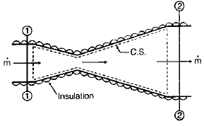
Throttling Device (Valve, Orifice, Porous Plug)
Throttling refers to flow through a restriction (small orifice, partially closed valve, capillary, porous plug) where a substantial pressure drop occurs without useful work extraction.

For an ideal throttling process:
- the process is very rapid and adiabatic (no heat transfer),
- changes in kinetic and potential energies are usually negligible,
- specific enthalpy remains constant across the device: h1 = h2.
Therefore throttling is an isenthalpic process. It is irreversible and commonly used in refrigeration expansion valves and pressure-reducing stations.
Turbine and Compressor
Turbine: a device where the fluid expands and performs shaft work; the fluid's enthalpy decreases and mechanical power is produced.
Compressor: a device where work is supplied to the fluid to increase its pressure; fluid enthalpy increases and mechanical power is consumed.
- The first law for steady-flow devices (per unit mass) is again
q - w = (h2 - h1) + (V22 - V12)/2 + g (Z2 - Z1)

For most turbomachinery (turbines and compressors) changes in kinetic and potential energy between inlet and outlet are negligible. If the device is adiabatic (q ≈ 0) the energy equation simplifies to
- w = h2 - h1
Rearranged for the shaft work done by the fluid (per unit mass):
w = h1 - h2
Thus:
- For a turbine, h1 > h2, so h1 - h2 is positive; the fluid produces shaft work (w positive by this convention). The shaft work produced per unit mass = h1 - h2.
- For a compressor, h2 > h1, so h2 - h1 is the work per unit mass required to compress the fluid. The shaft work required per unit mass = h2 - h1.
Note on sign conventions: some texts define w as work done on the fluid; others define w as work done by the fluid. Always state the convention before substituting numerical values. The relations above follow the convention that positive w denotes work produced by the fluid.


Heat Exchanger
- Heat exchanger: a device that transfers heat between two or more fluid streams. It can operate with fluids separated by a solid wall (e.g., shell-and-tube, plate heat exchangers) or with direct contact between the fluids.
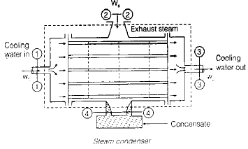
In most heat exchangers there is negligible shaft work and steady operation; the SFEE for each stream reduces to a balance of enthalpy change and heat transfer. If kinetic and potential changes are negligible, the energy change for stream 1 may be approximated by
q̇1 = ṁ1 (h2 - h1)
and similarly for stream 2, with heat balance ensuring q̇1 + q̇2 ≈ 0 for an ideal, adiabatic overall heat exchanger.
Summary and Practical Remarks
- Always choose a clear control volume and state sign conventions for heat and work before using SFEE.
- Common simplifications-neglect kinetic and potential energy changes when they are small compared with enthalpy changes; assume adiabatic conditions for insulated devices.
- Turbine/compressor: shaft work per unit mass ≈ enthalpy drop (turbine) or enthalpy rise (compressor).
- Nozzle/diffuser: trade-offs between enthalpy and kinetic energy; nozzle increases velocity, diffuser increases pressure.
- Throttling: isenthalpic and irreversible; used where pressure must be reduced without shaft work.
- Heat exchangers: transfer enthalpy between streams; individual stream energy balances use the SFEE with shaft work neglected in most applications.
FAQs on First Law Applied to Flow Processes
| 1. What is the First Law of Thermodynamics and how is it applied to flow processes in Mechanical Engineering? |  |
| 2. How is the First Law applied to flow processes in Mechanical Engineering? | |
| 3. Can you provide an example of how the First Law is used to analyze a flow process in Mechanical Engineering? | |
| 4. How does the First Law help in improving the energy efficiency of flow processes in Mechanical Engineering? | |
| 5. Are there any limitations or constraints in applying the First Law to flow processes in Mechanical Engineering? | |


