Gear Trains

Introduction
A gear train is a combination of two or more gears mounted on shafts and connected so as to transmit rotary motion and torque from one shaft to another. Gear trains are used to obtain desired changes in speed, torque and direction of rotation within a compact space. They are widely used in machines, gearboxes, clocks, machine tools and vehicle transmissions.
Types of gear trains
- Simple gear train - each shaft carries only one gear; axes of all gears are fixed relative to the frame.
- Compound gear train - one or more shafts carry two or more gears rigidly fixed together so that those gears have the same angular velocity.
- Reverted gear train - a special type of compound train in which the axis of the first and the last gear coincide (the driving and driven shafts are co-axial or coincident).
- Planetary (epicyclic) gear train - one or more gears (planet gears) revolve around another gear (sun) while also meshing with it; the axes of one or more gears move relative to the frame. These are compact and capable of large velocity ratios.
Simple gear train
In a simple gear train every gear is mounted on its own shaft and the axes of all gears are fixed in the frame. Motion is transmitted from the driving gear to the driven gear through intermediate gears (if any).
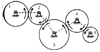
- A pair of externally meshing gears always rotate in opposite directions.
- All odd-numbered gears rotate in one direction and all even-numbered gears rotate in the opposite direction.
- Intermediate gears that only change the direction or centre-distance, without changing the overall speed ratio, are called idlers.
- A simple gear train may use spur or bevel gears depending on shaft orientation.
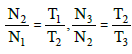
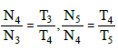
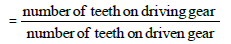
The magnitude of the speed ratio (the relation between angular speeds) in a simple gear train depends on the number of teeth (or pitch circle diameters) of the gears. For a simple series of gears, the overall ratio is the product of individual mesh ratios.

Speed Ratio =


In words: the angular speed ratio between the first and last gears equals the product of the intermediate gear ratios. Idler gears do not change the magnitude of this ratio; they only change the sense (direction) of rotation.
Compound gear train
A compound gear train contains one or more shafts that carry two or more gears rigidly fixed together and rotating with the same angular velocity. Because gears fixed on the same shaft share angular speed, compound trains allow large overall ratios using smaller gears and compact arrangements.
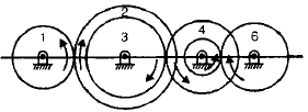
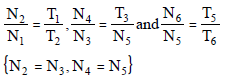
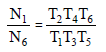
The overall train value (or velocity ratio) for a compound train is obtained by multiplying the individual gear pair ratios encountered from the driving gear to the driven gear. If gears on the same shaft are labelled so that meshing pairs are known, the speed ratio is the product of the ratios for those meshing pairs.

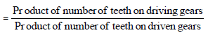
Speed Ratio
Reverted gear train
A reverted gear train is a compound train in which the axes of the first and last wheels coincide. This arrangement is used where the input and output shafts must be co-axial but a large speed reduction is required, for example in clocks and the back-gear of a lathe to obtain slow spindle speeds.
- When the first and last axes coincide, the pitch circle geometry imposes a condition relating pitch radii of the four gears in the simplest reverted four-gear arrangement.
- Such trains permit a compact layout with reversed direction where required.
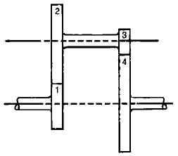
The pitch circle radii of the four gears in a reverted train satisfy the condition
r1 + r2 = r3 + r4

Epicyclic (planetary) gear trains
An epicyclic or planetary gear train is one in which one or more gears (planet gears) revolve about another gear (sun) while also meshing with it or with an annular (ring) gear. In epicyclic trains the axis of at least one gear moves relative to the frame, giving the train additional kinematic possibilities.
- Typical elements: sun gear (central gear), planet gears (mounted on a carrier and orbiting the sun), carrier (arm carrying planets), and ring (annulus) (internal gear that meshes with planets).
- Epicyclic trains are compact and can achieve large velocity ratios in a small space; they are widely used in automotive automatic transmissions, differential systems, clocks and speed reducers.
- If the ring gear is fixed, or if the carrier is held, different combinations of input and output produce different ratios and directions; the train generally has two degrees of freedom (two inputs produce a single output, or one input and one fixed element produce the result).
- Analysis is performed by considering relative angular velocities. A commonly used relation (Willis' equation) for a simple epicyclic train is
(ωs - ωc) / (ωr - ωc) = -Nr / Ns
where ωs, ωr and ωc are the angular velocities of the sun, ring and carrier respectively, and Ns, Nr are the number of teeth on the sun and ring. This relation expresses that the relative speeds about the carrier are inversely proportional to the corresponding tooth counts and the negative sign indicates opposite sense for external/internal meshing where applicable.
Methods of analysis include the relative velocity method (subtracting the carrier speed from all angular speeds to reduce to an equivalent simple gear train), and tabular or algebraic methods derived from the Willis relation. Careful accounting of sign (direction) and which element is held fixed is essential when using these methods.
Differential gear
A differential gear is a form of epicyclic arrangement used in vehicles so that the two driven wheels can rotate at different speeds while receiving drive from a common source. When a vehicle turns, the outer wheel travels a larger distance and therefore must rotate faster than the inner wheel; the differential provides this automatically while allowing both wheels to be driven.
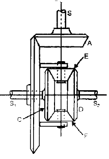
- Typical construction uses a pair of bevel gears on the wheel shafts and a set of planet (spider) gears mounted on a carrier driven by the engine through the gearbox; the carrier distributes torque while allowing relative rotation between the side gears.
- The differential can be considered as a device that adds and subtracts angular displacements: the wheel speeds are the sum and difference of carrier and relative epicyclic motions depending on load and turning.
Key relations and practical points
- For two meshing gears with numbers of teeth T1 and T2, the ratio of angular speeds is ω1 : ω2 = T2 : T1 (magnitudes). Direction reverses for external gears.
- For a series of externally meshing gears in a simple train the overall speed ratio is the product of successive mesh ratios; idler gears do not change the overall magnitude.
- In compound trains gears fixed on the same shaft share the same angular velocity; overall ratio is formed by multiplying mesh ratios for each shaft transition.
- Design considerations include centre distances, module selection (to ensure compatible tooth sizes), interference and undercut, lubrication, strength (tooth bending and surface stress) and accuracy of speed ratios.
- Planetary trains give high power density and multiple train configurations in a small volume but require careful assembly and bearing support for the rotating carrier and planet pins.
Applications
- Simple and compound trains - machine tools (lathes, milling machines), gearboxes for moderate speed changes, clocks.
- Reverted trains - situations requiring co-axial input and output with large reduction in a compact form (e.g., watch and clock trains, some lathe back gears).
- Epicyclic/planetary trains - automotive automatic transmissions, differential gearing, helicopter rotors, precision instruments and compact speed reducers.
Summary
Gear trains are fundamental mechanisms for changing speed, torque and direction between shafts. The main types - simple, compound, reverted and epicyclic - differ by how gears are arranged and which axes are fixed. Simple trains use single gears per shaft and idlers only change direction; compound trains use multiple gears on a shaft to achieve large ratios; reverted trains give co-axial input/output; epicyclic trains allow compact, high-ratio systems and are widely used in modern transmissions. Understanding tooth count relations, methods of analysis (product of mesh ratios, relative velocity or Willis' relation) and practical design constraints is essential for correct selection and design of gear trains.
FAQs on Gear Trains
| 1. What is a gear train and how does it work? |  |
| 2. What are the different types of gear trains? | |
| 3. What are the advantages of using gear trains in mechanical systems? | |
| 4. How can gear trains be used in different applications? | |
| 5. What are some common issues or challenges faced with gear trains? | |


