Dynamics Force Analysis & Flywheel | Mechanical Engineering SSC JE (Technical) PDF Download

Dynamic forces are associated with accelerating masses.
- D' Alembert's principle states that the inertia forces and couples, and the external forces and torques on a body together give statical equilibrium.
- Inertia is a properly of matter by virtue of which a body resists any change in velocity.
Inertia force, F1 = – m fg
m = mass of body
fg = acceleration of centre of mass of the body
- Inertia couple resists any change in the angular velocity Inertia force, Ci = - Ig. a
Ig = moment of inertia about an axis passing through centre of mass G and perpendicular to plane of rotation of the body
a = angular acceleration of the body.
- Let F1, F2, F3 etc. = external forces on the body
Tg1, Tg2, Tg3 etc. = external torques on the body about centre of mass G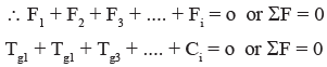
Thus a dynamic analysis problem is reduced to one requiring static analysis.
- The perpendicular displacement h of the force from centre of mass is such that the torque so produced is equal to the inertia couple acting on the body.

where k = radius of gyration
Velocity And Acceleration of Piston
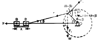
If the crank OA rotates in the clockwise direction
l and r = lengths of connecting rod and crank
Let, × = displacement of piston from inner dead centre.
θ = angle turned by crank from inner dead centre.
n = l/r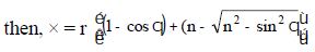
then maximum value of sin2q can be unity, and (n2 >>1), for large connecting rod.
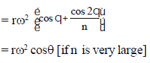
So × = r (1 – cosθ)
This is the expression for a simple harmonic motion. Thus the Piston executes a simple harmonic motion when the connecting rod is large.
- Velocity of Piston,
v =
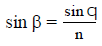
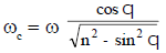
- Angular velocity and Angular Acceleration of connecting rod:
- Angular acceleration of connecting rod:
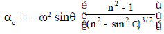
The negative sign indicates that the sense of angular acceleration of the rod is such that it tends to reduce the angle b.
Piston Effort (Effective Driving Force)
- In reciprocating engines, the reciprocating masses accelerate during the first half of the stroke and the inertia force due to the same tends to resists the motion. Thus net force on the piston decreased.
- During the later half of the stroke, the reciprocating masses decelerate and the inertia force opposes this deceleration or the inertia force acts in the direction of the applied gas pressure and thus increase the effective force on the piston.
- In a vertical engine, the weight of the reciprocating masses assists the piston during the out stroke (down stroke), thus increasing the piston effort by an amount equal to the weight of the piston.
- During the in stroke (upstroke) piston effort is decreased by the same amount.
Let, A1 = area of Piston (cover end)
A2 = area of piston end
p1 = pressure on cover end
p2 = pressure on piston end
m1 = mass of reciprocating parts
Force on piston Fp = p1A1 – p2A2
Inertia force; Fb = mf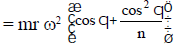
Net force on piston F = Fp – Fb
- Crank Effort: Crank effort is the net effort (force) applied at the crank pin perpendicular to the crank which gives the required turning moment on the crank shaft.
Let, Ft = crank effort
Fc = force on connecting rod
Ft = Fc sin (θ + β)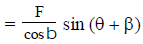
- Turning Moment on Crankshaft
T = Ft × r
- Inertia of connecting rod: As the motion of connecting rod is not linear.
The mass of connecting rod can be replaced by two point masses at two point, if it is ensured that the two masses together have the same dynamical properties as before.
FLYWHEEL
Function
- A flywheel used in machines serve as a reservoir, which stores energy during the period when supply of energy is more than the requirement, and release it during the period when the requirement of energy is more than the supply. Flywheel does not maintain a constant speed, it simply reduce fluctuation of speed.
Turning Moment Diagram
- The turning moment diagram is the graphical representation of the turning moment or crank-effort. The turning moment is taken as ordinate and crank angle as abscissa.
Turning Moment diagram for single cylinder four stroke engine
- In case of a four-stroke internal combustion engine, the diagram repeats itself after every two revolution instead of one revolution as for a steam engine.
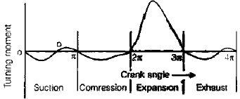
- The pressure inside the engine cylinder is less than the atmoshperic pressure during the suction stroke, therefore a negative loop is formed.
- During the compression stroke, the work is done on the gases, therefore a higher negative loop is obtained.
- During the expansion or working stroke, the fuel burns and the gases expand, therefore a large positive loop is obtained. In this stroke, the work is done by the gases.
- During exhaust stroke, the work is done on the gases, therefore a negative loop is formed.
T-M diagram for multi-cylinder engine
- The turning moment diagram for a single cylinder, engine varies considerably and a greater variation of the same is observed in case of a four stroke, single cylinder engine. For engines with more than one cylinder, the total crank shaft torque at any instant is given by the sum of the torques developed by each cylinder at the instant.
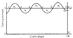
Fluctuation of Energy
- The energies of the flywheel corresponding to positions of the crank are as follows:
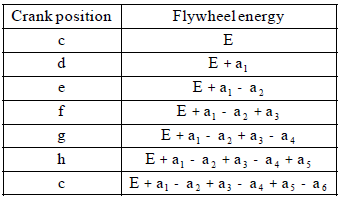
From the two values of the energies of the flywheel corresponding to the position c, it is concluded that
a1 – a2 + a3 – a4 + a5 – a6 = 0
- The greatest of these energies is the maximum kinetic energy of the flywheel and for the corresponding crank position, the speed is maximum.
- The least of these energies is the least kinetic energy of the flywheel and for the corresponding crank position, the speed is minimum.
Fluctuation of Speed
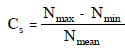
- The difference between the maximum and minimum speeds during a cycle is called maximum fluctuation of speed.
- The ratio of maximum fluctuation of speed to the mean speed is called coefficient of fluctuation of speed (Cs).
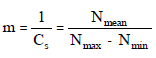
- Coefficient of Steadiness: The reciprocal of the coefficient of fluctuation of speed is known as coefficient of steadiness and is denoted by m.
Maximum fluctuation of speed
∴ Maximum fluctuation of energy
DE = Maximum energy – Minimum energy
We can also write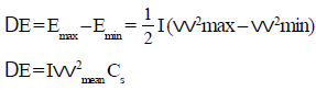
Here, I = Mass moment of inertia of the flywheel about its axis of
rotation
wmax = Maximum angular speed during cycle
wmin = Maximum angular speed during cycle
wmean =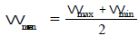
during cycle
- Coefficient of Fluctuation of Energy (CE)
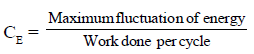
Work done per cycle
Work done per cycle = Tmean × q
Work, Tmean is mean torque,
q is angle turned is one cycle
= 2p, in case of two stroke engine
= 4p, in case of 4 stroke engine
|
5 videos|103 docs|59 tests
|
FAQs on Dynamics Force Analysis & Flywheel - Mechanical Engineering SSC JE (Technical)
| 1. What is dynamics force analysis in mechanical engineering? |  |
| 2. How is flywheel used in mechanical engineering? | |
| 3. What are the benefits of using flywheels in mechanical systems? | |
| 4. How do engineers analyze the dynamics forces in mechanical systems? | |
| 5. What are some practical applications of dynamics force analysis and flywheel in mechanical engineering? | |


Exam
,Important questions
,Dynamics Force Analysis & Flywheel | Mechanical Engineering SSC JE (Technical)
,Extra Questions
,shortcuts and tricks
,practice quizzes
,ppt
,Semester Notes
,Sample Paper
,Dynamics Force Analysis & Flywheel | Mechanical Engineering SSC JE (Technical)
,Previous Year Questions with Solutions
,study material
,Summary
,past year papers
,MCQs
,mock tests for examination
,video lectures
,Objective type Questions
,Viva Questions
,Dynamics Force Analysis & Flywheel | Mechanical Engineering SSC JE (Technical)
,Free
;


Dynamics Force Analysis & Flywheel Free PDF Download
Importance of Dynamics Force Analysis & Flywheel
Dynamics Force Analysis & Flywheel Notes
Dynamics Force Analysis & Flywheel Mechanical Engineering Questions
Study Dynamics Force Analysis & Flywheel on the App
|
© EduRev
|
Education Revolution
|


|


