Shear Force & Bending Moment


Basic definitions
Shear force at a cross-section of a beam is the algebraic sum of the transverse forces on either side of the section. Practically, it is the internal force that tends to produce sliding of one part of the beam relative to the other about the cross-section.
Bending moment at a cross-section of a beam is the algebraic sum of the moments of the forces on either side of the section about that section. It is the internal moment that tends to bend the beam at the section.
Beam is a structural member designed primarily to resist transverse loads (loads perpendicular to the longitudinal axis). It transfers loads to supports by shear forces and bending moments acting along its length.
Classification of beams
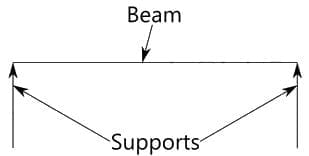
- Simply supported beam - supported by a pin at one end and a roller at the other; both ends are free to rotate but cannot translate vertically. It is one of the most common and simplest beams.
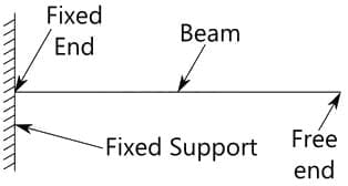
- Cantilever beam - fixed at one end and free at the other. The fixed end provides bending moment and shear resistance; the free end is unsupported.
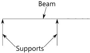
- Overhanging beam - a beam with one or both ends projecting beyond the supports.
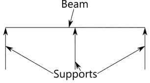
- Continuous beam - a beam with more than two supports along its length.
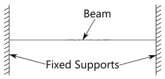
- Fixed beam - both ends are fixed against rotation and translation.
Sign conventions
- Shear force (V): Adopt a sign convention and apply it consistently. A commonly used convention is: if the left portion of the beam (when cut) tends to move up relative to the right portion, the shear is taken as positive. Conversely, if the left portion tends to move down, the shear is taken as negative.
- Bending moment (M): Positive (sagging) when the bending causes the beam to sag (concave upwards on the top surface); negative (hogging) when the bending causes the beam to hog (concave downwards on the top surface).
- Note: Maximum bending moment in a span typically occurs at locations where the shear force changes sign (i.e., where V = 0), provided the bending moment is a smooth function there.
Relations between load, shear and moment
For a beam with distributed load intensity w(x) (positive downward), shear force V(x) and bending moment M(x) satisfy the differential relations:
dV/dx = -w(x)
dM/dx = V(x)
These relations are very useful when constructing Shear Force Diagrams (SFD) and Bending Moment Diagrams (BMD).
Procedure to draw Shear Force Diagram (SFD) and Bending Moment Diagram (BMD)
- Draw the beam, supports and applied loads (point loads, couples, UDLs, varying loads).
- Determine reaction forces at supports using equilibrium conditions: ΣFx = 0, ΣFy = 0, ΣM = 0.
- Take a cut at a section x from a chosen origin and consider either the left or right portion.
- Write algebraic sum of vertical forces to obtain V(x). Write algebraic sum of moments about the cut to obtain M(x).
- Plot V(x) along the beam length to obtain the SFD; plot M(x) to obtain the BMD.
- Use the relations dV/dx = -w(x) and dM/dx = V(x) to determine slopes and curvature of diagrams: a concentrated load produces a jump in V(x) and a change of slope in M(x); a concentrated couple produces a jump in M(x) without changing V(x); a uniform distributed load produces a linear variation in V(x) and a parabolic variation in M(x).
SFD and BMD for Cantilever Beams
Case (i): Cantilever of length l carrying a concentrated load W at the free end
Consider positive shear on the left portion as upward and positive moment as sagging. For a section at distance x from the free end (measured along the beam towards the fixed end):
Shear: V(x) = +W
Bending moment: M(x) = -W x
Maximum bending moment occurs at the fixed end (x = l): Mmax = -W l
Case (ii): Cantilever of length l carrying a uniformly distributed load w (per unit length) over the whole length
For section at distance x from the free end:
Shear: V(x) = +w x
Bending moment: M(x) = -w x2 / 2
Maximum shear occurs at the fixed end (x = l): Vmax = +w l
Maximum bending moment occurs at the fixed end (x = l): Mmax = -w l2 / 2
Case (iii): Cantilever of length l carrying a uniformly distributed load w over the whole length and a concentrated load W at the free end
For section at distance x from the free end:
Shear: V(x) = +w x + W
Bending moment: M(x) = -(w x2 / 2 + W x)
Maximum shear at fixed end: Vmax = w l + W
Maximum bending moment at fixed end: Mmax = -(w l2 / 2 + W l)
Case (iv): Cantilever of length l carrying a uniformly distributed load w over a length a measured from the free end (i.e., load applied from free end up to distance a)
For a section located at x from free end, two regions exist:
Region 1 (0 ≤ x ≤ a):
V(x) = +w x
M(x) = -w x2 / 2
Region 2 (a ≤ x ≤ l):
V(x) = +w a
M(x) = -(w a (x - a) + w a2 / 2) = -w a x + w a2 / 2
Case (v): Cantilever of length l carrying a triangular load varying from zero at free end to w (per unit length) at fixed end
Intensity at a distance measured from free end increases linearly. For section at distance x from free end:
Load on portion from free end to x equals area of triangle with base x and height (w x / l).
Shear: V(x) = + (w x2) / (2 l)
Bending moment: M(x) = - (w x3) / (6 l)
Maximum shear at fixed end x = l: Vmax = +w l / 2
Maximum bending moment at fixed end x = l: Mmax = - w l2 / 6
Case (vi): Cantilever carrying triangular load varying from w at free end to zero at fixed end (reverse triangular)
For section at distance x from free end, derive shear and moment by integrating the intensity distribution. The resulting expressions are cubic/parabolic functions of x; the maximum values occur at the fixed end and must be computed by direct substitution of x = l.
SFD and BMD for Simply Supported Beams
Important note
Maximum bending moment in a span normally occurs where the shear force is zero (V = 0), or at points of load application/supports depending on discontinuities.
Case (i): Simply supported beam of span l carrying a concentrated load W at mid-span
Reactions at the supports A and B each equal W/2.
For a section at distance x measured from left support A (0 ≤ x ≤ l/2):
V(x) = +W/2
M(x) = + (W/2) x
For a section at distance x where l/2 ≤ x ≤ l:
V(x) = -W/2
M(x) = + (W/2) (l - x)
Maximum bending moment occurs at mid-span x = l/2: Mmax = W l / 4
Case (ii): Simply supported beam carrying a concentrated load W at an eccentric position (distance a from left support and b from right support; a + b = l)
Reactions:
RA = W b / l
RB = W a / l
For a section at distance x from left support:
Between A and the load (0 ≤ x < a): V(x) = +W b / l
Between load and B (a < x ≤ l): V(x) = -W a / l
Moment expressions depend on x and the position of load; maximum bending moment under the load at x = a is Mmax = W a b / l.
Case (iii): Simply supported beam carrying a uniformly distributed load w (per unit length) over the whole span
Total load W = w l.
Reactions at supports: RA = RB = w l / 2.
For a section at distance x from left support:
V(x) = w l / 2 - w x
M(x) = w l x / 2 - w x2 / 2
Set V(x) = 0 to find location of maximum moment: x = l/2.
Maximum bending moment at mid-span: Mmax = w l2 / 8 = W l / 8.
Case (iv): Simply supported beam with load intensity varying symmetrically from zero at each end to w at mid-span (triangular peaked at mid-span)
The load is symmetric; reactions are equal. The bending moment curve is cubic/parabolic form. For a symmetric triangular load of total resultant W, the maximum moment is:
Mmax = W l2 / 12
(Derivation uses area and centroid of triangular load applied to each half span and equilibrium.)
Case (v): Simply supported beam carrying a load whose intensity varies uniformly from zero at one end (A) to w at the other end (B)
For a section at distance x from A with beam length l:
Shear and moment expressions are obtained by integrating the intensity distribution; typical expressions are:
V(x) = (w l x / 6) - (w x2 / 2)
M(x) = (w l x2 / 6) - (w x3 / 6)
Maximum bending moment occurs at x = l / 3 from A, and the value is Mmax = w l2 / 9.
Simply supported beam with overhangs (uniformly distributed load over entire length)
Consider beam with span AB = l and equal overhangs length a on both sides (EF are supports at A and B positions as shown in typical figure). For a uniformly distributed load w over the whole beam, expressions for shear and moment in different regions can be written by taking appropriate sections.
Shear in overhang region EA at a distance x from E: V(x) = -w x
Shear in main span AB at distance x from A: V(x) = w (l/2 + a) - w x (with signs and algebra depending on chosen origin)
Moment in EA: M(x) = -w x2 / 2
Moment in AB: M(x) = (w/2) x (l + 2 a) - w x2 / 2 - w a x (simplify according to coordinates)
Points of contraflexure (where M = 0) occur when the bending moment changes sign within a span. For certain relations between l and a, the number and position of contraflexure points vary:
- If l2 > 4 a2, two points of contraflexure occur symmetrically about midspan.
- If l2 = 4 a2, contraflexure points coincide at the centre and BM at centre is zero.
- If l2 < 4 a2, no sign change in BM inside the span; BM is of hogging type in the interior.
Rule about distributed loads and diagram shapes
- A concentrated vertical load produces a jump (discontinuity) in the shear diagram equal to the magnitude of the load and a change in slope of the bending moment diagram.
- A couple (pure moment) produces a jump in the bending moment diagram equal to the couple; shear diagram is unaffected by a pure couple.
- A uniformly distributed load produces a linear variation in the shear diagram and a parabolic variation in the bending moment diagram.
Bending moment and shear force due to a couple
Case (a) Cantilever with an applied end couple M at free end:
There is no shear force due to a pure couple; V(x) = 0 everywhere due to the couple alone.
Internal bending moment is constant and equal to the applied couple (sign depending on direction): M(x) = -M (or +M depending on sign convention).
Case (b) Simply supported beam with an applied internal couple M at some section C:
Shear force due to the couple is zero except for reactions needed to maintain equilibrium; however, when treating left and right segments separately, the couple produces equal and opposite bending moments on either side of the cut. If the couple is located at distance a from the left support and b from the right support:
Left portion bending moment near the cut: M_left = -M + (reactions contribution)
Right portion bending moment near the cut: M_right = +M + (reactions contribution)
Shear due solely to the couple is zero in the cut portion; in drawings, the BMD shows a vertical jump equal to the magnitude of the couple at the location of the couple.
Practical remarks and applications
- SFD and BMD are essential for locating points of maximum shear and maximum bending moment which determine design sections for bending, shear, and deflection checks.
- Use the relation dM/dx = V(x) to locate maxima and minima of bending moment (set V = 0 and check sign change).
- Sign conventions must be fixed at the start and used consistently across the whole problem; check signs of reactions and internal forces carefully.
- For varying loads, find resultant (area under intensity diagram) and its point of action (centroid) to simplify reaction and moment calculations.
Example guidance (general method)
To solve any beam SFD/BMD problem, follow these calculational steps:
Draw the loaded beam and supports. Mark distances and load intensities.
Compute reactions at supports by applying equilibrium equations: ΣFy = 0 and ΣM = 0.
Cut the beam at a general section x and consider equilibrium of the left (or right) part to obtain V(x) and M(x).
Express V(x) and M(x) as functions of x. Use dV/dx = -w(x) and dM/dx = V(x) to check correctness.
Plot V(x) and M(x) noting jumps at point loads and couples, linear slopes under UDLs and parabolic shapes for moments under distributed loads.
Terminology recap
- Sagging - bending that produces tensile stresses at the bottom fibres and compressive at the top (positive moment by convention here).
- Hogging - bending that produces tensile stresses at the top fibres and compressive at the bottom (negative moment by convention here).
- Contraflexure point - location along the beam where bending moment is zero and its sign changes.
FAQs on Shear Force & Bending Moment
| 1. What is shear force and bending moment in mechanical engineering? |  |
| 2. How are shear force and bending moment related? | |
| 3. How can shear force and bending moment be calculated? | |
| 4. What are the applications of shear force and bending moment analysis? | |
| 5. What are the typical signs of shear force and bending moment in beams? | |


