Metal Cutting - 2


Metal Casting
Up milling and Down milling
In up milling (conventional milling) the cutter and the workpiece move in opposite directions at the point of contact. In down milling (climb milling) the cutter and the workpiece move in the same direction at the point of contact.
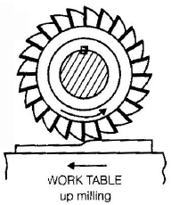
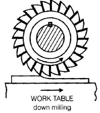
In up milling the chip thickness varies from minimum to maximum across the cutting engagement. Before cutting begins the cutting edge tends to rub on the finished surface, so the surface finish is usually poorer than in down milling. Hot chips may remain in the tooth space for a longer time in up milling. In fixtures subject to tensile forces, up milling may be less favourable; the opposite is true in down milling where compressive forces are applied at the work-fixture interface.
Powder Metallurgy
Definition. Powder metallurgy is the set of processes used to manufacture parts from metal powders. It is particularly useful for producing parts that cannot be made by conventional melting/alloying methods or where near-net shapes, porosity control, or unique combinations of materials are required.
Major applications of powder metallurgy:
- Filaments and components for lamps and heating tubes.
- Cutting tools and grinding-wheel inserts.
- Nozzles for abrasive-jet machining.
- Porous or self-lubricating bearings.
- Filters used in casting and other processes.
- Friction materials (for example, components in anti-lock braking systems).
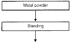
Sequence of processes in powder metallurgy
1. Methods of making metal powders
- Mechanical crushing and pulverising: Brittle materials can be reduced to powder by crushing and milling. Ductile materials may be embrittled (by cooling) first to assist crushing.
- Atomisation: Molten metal is disintegrated into droplets which solidify as powders. This is commonly done by gas or water atomisation, or by centrifugal atomisation from a rotating disk. Plasma spraying also can produce metal powders.
- Corrosion or chemical displacement: Some powders are obtained by controlled chemical dissolution and subsequent precipitation; this method is slower and used in specialised cases.
2. Blending
Lubricants and other additives are mixed with powders to coat particle surfaces. The lubricant improves powder flow and packing and aids ejection from compacting tooling. The mixed powder is then pressed to form a green compact-a freshly prepared compact having sufficient handling strength but not yet fully densified.
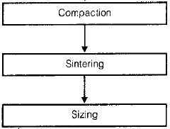
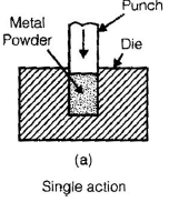
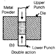
3. Compaction
Compaction gives the green compact its initial strength. Typical methods include single-action and double-action mechanical presses and isostatic pressing. Hot isostatic pressing (HIP) combines high temperature with isostatic pressure for improved densification.
Smaller particle size increases contact area and promotes diffusion during sintering; therefore finer powders generally yield stronger compacts. Double-action presses and isostatic pressing produce more uniform density and properties than single-action pressing.
4. Pre-sintering and Sintering
(a) Pre-sintering. The green compact is heated to burn out lubricants and binders; the lubricant should leave no harmful residue. Pre-sintering encourages local bonding and reduces distortion prior to final sintering. When presintering is combined with compaction at elevated temperature it is called hot isostatic pressing. In some cases rougher particles interlock better in the compact and may improve initial strength.
(b) Sintering. The compact is heated to about 60-70% of the melting point of the base metal to promote diffusion bonding between particles. Low melting constituents or binders may liquefy and fill pores; for mixtures with widely differing melting points multiple-stage heating may be used. After sintering the part attains greater hardness; extensive machining is generally avoided but some sizing and simple finishing operations may be carried out. Because tooling and presses are expensive, powder metallurgy is most economical for mass production.
Jigs and Fixtures
Auxiliary devices used to support, locate and hold workpieces during manufacturing operations:
- Jig: A device that locates the workpiece and guides the cutting tool. Commonly used in drilling, reaming and similar operations.
- Fixture: A device that locates and holds the workpiece but does not guide the tool. Fixtures are widely used in milling, shaping and other operations where the tool movement is controlled by the machine.

Screw Thread Manufacturing
Common methods for producing screw threads are:
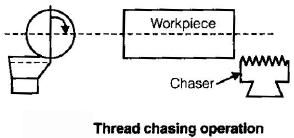
1. Thread chasing
Producing screw threads on a lathe is commonly called thread cutting or thread chasing. In high-volume automated manufacture, specialised automatic lathes (for example, Swiss automatic machines) feed and rotate wire to cut threads and then part the workpiece from the wire.
2. Die threading
External threads on rods and pipes are cut using hand dies or machine dies. For large diameter pipes or heavy-duty applications, die threading is limited by tool size and leverage. Changes in thread form or pitch require different dies.
3. Tapping
Tapping is the process of producing internal threads. Sets of taps (usually a taper tap, intermediate tap and bottoming tap) are used to cut threads in blind or through holes. Accurate threads require correct tap selection and control.
4. Thread milling
Thread milling is used where thread termination is close to a shoulder or for very large diameters. A rotating cutter interpolates the thread form into the hole or on the shaft.
5. Thread rolling
Thread rolling forms threads by plastic deformation. A blank is pressed between flat or circular dies; the material is displaced to form the thread profile. The process increases strength by cold-working the surface and produces good surface finish and fatigue properties.
Materials for Gears
- Cast iron: Used for large gears made by casting. Care is needed when gears are subject to fatigue loading.
- Steel: Widely used where high load-carrying capacity and toughness are required.
- Bronze: Preferred for worm gear wheels because of good sliding resistance against steel worms.
- Plastics: Used where quiet operation, corrosion resistance or low cost is required (e.g., toys).
- Aluminium: Used where light weight is important but power transmission capacity is limited.
- Nylon: Employed in office machines (for example, photocopiers) for quiet running and moderate loads.
Machining of Gears
Gear milling
Gears may be milled using form cutters or by generating methods. Milling can produce spur, helical and bevel gears, but accuracy is lower than with dedicated gear machines.
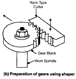
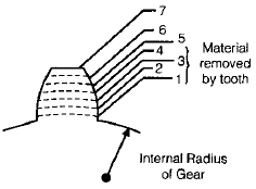
Gear shaping
Shaping with a rack-type cutter requires indexing after a cut is made; this yields moderate accuracy. A pinion-type cutter engages the work and cutter with continuous rotary motion; this giving higher accuracy and permitting internal gear cutting. Both spur and helical gears can be produced by shaping.
Broaching
Broaching produces internal splines and gear-like profiles by pulling or pushing a multi-tooth broach through a pilot hole; all teeth are formed in a single pass. For external profiles, pot broaching is used. Broaching can produce both spur and helical profiles where applicable.
Gear hobbing
Hobbing uses a helical cutting tool called a hob which resembles a splined screw. The kinematic relationship between hob and work generates the gear tooth form. By changing the relative helix angle, hobbing can produce different helix angles on the work. Hobbing cannot normally produce internal gears or teeth very close to shoulders. It is one of the fastest methods to produce gears.
Non-traditional (Unconventional) Machining Methods
Conventional machining removes material by plastic shear (chip formation) or abrasion. When parts are very hard or brittle, have complex shapes, small features, or require superior surface finish and tight tolerances, unconventional methods are used. Typical reasons include:
- The material is very hard, very brittle, or has properties that make conventional cutting uneconomic.
- The geometry is complex (internal profiles, very small diameter holes, intricate shapes).
- Surface finish or dimensional tolerances are stricter than those achievable by conventional methods.
| Energy | Mechanics of material removal | Source | Process |
|---|---|---|---|
| Mechanical | Plastic shear; erosion | Mechanical motion of tool/job; mechanical/fluid motion | Conventional machining; AJM, USM |
| Electrochemical | Ion displacement | Electric current | ECM |
| Mechanical + electrochemical | Plastic shear and ionic displacement | Electric current and mechanical motion | ECG |
| Chemical | Corrosive reaction | Corrosive agent | Chemical machining (CHM) |
| Thermal | Fusion and vapourisation | Electric spark | EDM |
| High speed electrons | EBM | ||
| Powerful radiation | LBM | ||
| Ionised substance | IBM | ||
| High temperature plasma | PAM | ||
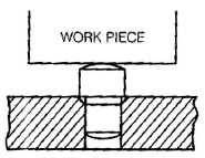
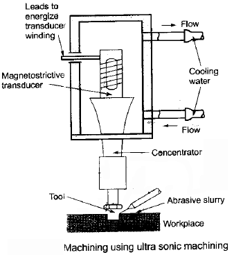
Ultrasonic Machining (USM)
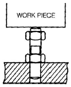
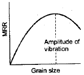
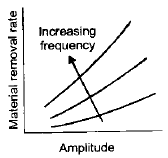
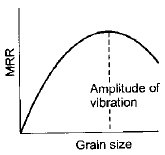
Principle. Ultrasonic machining uses a vibrating tool (typically at ultrasonic frequencies above human hearing) to transmit repeated impacts of abrasive particles against the work surface. Abrasives are carried in a liquid slurry and are hammered by the vibrating tool perpendicular to the surface, removing material by microchipping and erosion.
- A slurry of abrasive grains (commonly silicon carbide or boron carbide) is suspended in a fluid; water is most common, but other liquids or oils may be used.
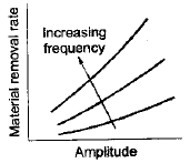
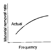
- The tool vibrates at ultrasonic frequencies and is gradually fed towards the work; each abrasive particle impacts and removes minute chips.
- USM is particularly effective for brittle or hard materials such as ceramics, carbides, precious stones and hardened steels.
In brittle materials, impact stresses cause microchipping and progressive erosion. USM produces good surface finishes and can machine non-conductive and very hard materials.
Advantages:
- Low noise when compared with many thermal processes.
- Equipment can be operated by semi-skilled labour.
- Negligible heat generation at the workpiece.
- Good surface finish and dimensional accuracy for many applications.
- Can machine non-conductive materials.
Disadvantages:
- Low material removal rate.
- High specific energy consumption.
- Soft ductile materials are difficult to machine effectively.
(a)
(b)
Applications:
- Die pre-shaping and finishing.
- Machining of hard carbides, glasses and gemstones.
- Dental applications and fine finishing of delicate components.
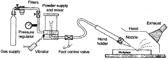
Abrasive Jet Machining (AJM)
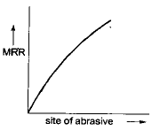
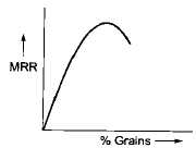
Principle. AJM uses a high-velocity stream of abrasive particles carried by a gas (air, nitrogen or carbon dioxide) directed at the workpiece. Material removal occurs by erosion from the high-speed particle impacts.
- The abrasive particles are accelerated by high-pressure gas and directed through a nozzle onto the work surface.
- AJM is used for cutting small holes, trimming, deburring, beveling, removing oxides and cleaning complex or fragile surfaces.
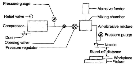
Typical operating parameters: gas supply pressures on the order of 850 kPa and jet velocities up to about 300 m/s. Nozzles are usually made from wear-resistant materials such as tungsten carbide or silicon carbide. Abrasive particle size is commonly in the range 10-50 μm. Because the free abrasive tends to round corners, design for AJM should avoid sharp internal corners; holes tend to be tapered.
AJM produces airborne particulates and dust hazards; these are reduced or eliminated by using abrasive water-jet machining where abrasives are mixed in water and the jet is contained.

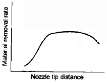
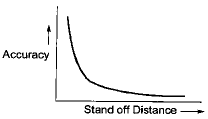
Nozzle Tip Distance (NTD)
- The distance between the workpiece and the nozzle tip is called the nozzle tip distance. Typical values range from about 7 mm to 13 mm.
- Nozzles suffer considerable wear and are therefore made of hard materials such as tungsten carbide, ceramics or diamond-coated inserts.


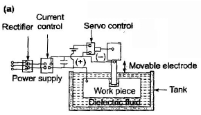
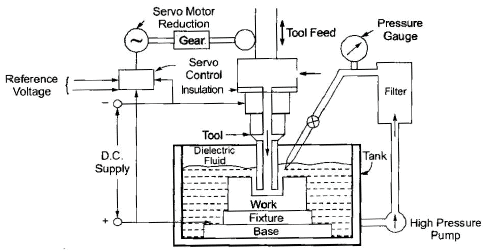
Electric Discharge Machining (EDM)
Principle. EDM (also called spark erosion machining) removes material by a sequence of electrical discharges (sparks) between a shaped tool (electrode) and the workpiece immersed in a dielectric fluid. Each spark produces localized heating that melts and vaporises a minute volume of work material.
Operation. A shaped electrode and the workpiece are connected to a power supply and submerged in a dielectric (electrically insulating) fluid. When the potential difference is sufficient, transient sparks occur across the gap, removing tiny amounts of metal. Typical voltage ranges are from about 50 V to 380 V, currents from 0.1 A to several hundred amperes, and pulse repetition rates from about 50 kHz to 500 kHz. The dielectric flushes away eroded particles.
Common dielectric fluids include mineral oils, kerosene and specially treated deionised water (in some applications). Because EDM is a thermal process rather than mechanically removing chips, the hardness, strength and toughness of the workpiece have less influence on material removal rate. Increasing discharge energy (higher current or longer pulses) increases removal rate but also surface roughness. Tool wear affects dimensional accuracy and is influenced by the melting points and thermal properties of the electrode and work materials.
Graphite electrodes are widely used because of good machinability, reasonable wear characteristics and low cost. Copper and copper-alloy electrodes give good conductivity and surface finish. Tool wear can be reduced by optimising polarity and process parameters.
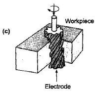
Process capabilities
EDM is used to produce complex cavities, dies, narrow slots, small deep holes (wire EDM or using a thin electrode), turbine blades and other intricate shapes with good accuracy and repeatability.
Uses of dielectric fluid
- Flush cut material and eroded particles from the spark gap.
- Promote controlled sparking and maintain stable discharges.
- Act as a coolant and insulator.
Tool materials for EDM
- Copper and copper alloys.
- Graphite.
- Tungsten and other conductive materials depending on application and wear requirements.
Wire cut EDM
- Used for cutting sheet and plate into complex shapes with a continuously moving wire electrode.
- The work table provides X-Y motion to follow the desired contour.
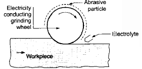
Electric Discharge Grinding (EDG)
EDG is similar to EDM but uses a rotating wheel (often graphite) as the electrode. The workpiece and wheel are immersed in dielectric fluid and the work is fed past the wheel under servo control. EDG is used to grind carbide and steel without wheel loading, to grind thin sections without distortion and to grind brittle parts without fracturing.
Applications:
- Grinding hard or difficult to grind materials.
- Producing complex profiles where conventional abrasives would load or chatter.
Electrochemical Machining (ECM)
Principle. ECM is the reverse of electroplating. The workpiece is the anode and the tool is the cathode. An electrolyte conducts current between tool and work; metal dissolves from the workpiece surface by controlled anodic dissolution. The cavity produced is the electrochemical image of the tool shape.
Main functions of the electrolyte:
- Complete the electrical circuit and allow large currents to pass between tool and workpiece.
- Remove heat and reaction products from the gap.
- Carry away metal ions and prevent plating of material onto the tool.
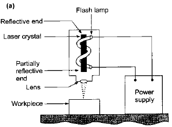
Laser Beam Machining (LBM)
Principle. LBM uses a highly focused laser beam to deliver optical energy to the work surface. The absorbed energy melts and vapourises material in a controlled manner. LBM does not require vacuum and can machine a wide range of metallic and non-metallic materials.
- Common industrial lasers include: CO₂ lasers (continuous or pulsed), Nd:YAG (neodymium), Nd:glass/ruby lasers and excimer lasers.
- Important physical parameters are surface reflectivity, thermal conductivity, specific heat and latent heats of melting and evaporation. Lower values of these parameters generally improve process efficiency.
- Laser cutting produces a kerf (slot width) and a heat-affected zone (HAZ); in critical applications the HAZ may require removal or post-heat treatment.

Laser beams are often used with an assist gas (oxygen, nitrogen or argon) to improve cutting by blowing away molten material and to enhance oxidation cutting for certain metals. High-pressure assist gas is commonly used for stainless steel and aluminium to produce oxide-free edges and improve weldability.
Electron Beam Machining (EBM)
Principle. EBM uses a focused beam of high-velocity electrons accelerated by high voltage (typically 50-220 kV) to strike the work surface and convert kinetic energy to heat, causing melting and vapourisation. Electrons may be accelerated to speeds of roughly 50%-80% of the speed of light.
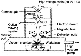
EBM requires a vacuum chamber to avoid electron scattering, which limits its use compared with laser cutting. EBM provides very fine kerf widths and excellent surface finish for metals. The process produces X-rays and requires specialised shielding and trained operators.
Note:
- Material removal rate (MRR): ECM > EDM > USM (typical ranking).
- Tool wear: USM > EDM > ECM (typical ranking).
Water Jet Machining
- Pure water jets (no abrasives) are used to cut materials such as wood, textiles, rubber, coal, concrete and leather by erosion.
- High-velocity water jets convert kinetic energy into localised stresses; when these stresses exceed the material strength, erosion and removal occur.
- Abrasive water-jet machining (AWJ) mixes abrasive particles in the water stream for cutting metals, ceramics and other hard materials.
Plasma Arc Machining (PAM)
Principle. Plasma is an ionised, highly conductive gas at very high temperature. In PAM a plasma jet generated by an electric arc is forced through a nozzle and impinges on the workpiece, heating, melting and removing material. The arc is established between an electrode and an anode/nozzle; a flowing gas passed through the arc becomes ionised and forms plasma.
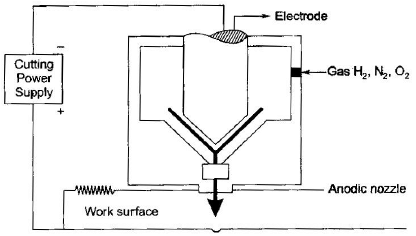
The arc electrons collide with gas molecules, causing ionisation and increased conductivity. Recombination of ions and electrons releases additional heat. The resulting high-temperature plasma jet removes material by rapid heating and by blowing away molten metal with the jet.
- Applications: Cutting and profiling of conducting materials such as steel, stainless steel and superalloys.
- Limitations: Lower dimensional accuracy than some non-thermal processes; heat-affected zones and taper can occur.
FAQs on Metal Cutting - 2
| 1. What are the different methods for metal cutting? |  |
| 2. What factors should be considered when selecting a metal cutting method? | |
| 3. What are the advantages of laser cutting for metal? | |
| 4. What safety precautions should be taken when performing metal cutting? | |
| 5. What are some common challenges in metal cutting? | |


