Bending Stresses in Beams

Theory of Pure Bending
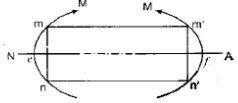
Pure bending refers to the state of bending in a beam in which bending moment is present but shear force is negligible over the length considered. The principal observations and conclusions from the theory of pure bending are given below.
- Plane sections originally parallel to each other remain plane and parallel after bending (they do not warp). This is the plane sections remain plane assumption.
- Fibres on the convex side elongate and fibres on the concave side shorten. There exists an intermediate layer where there is no change in length; this layer is the neutral axis (N.A.). The neutral axis passes through the centroid of the cross-sectional area for homogeneous sections.
- The longitudinal strain in a fibre is proportional to its distance from the neutral axis. Therefore strain varies linearly with distance from N.A., and hence stress (within elastic limit) also varies linearly with distance from N.A.
- Under bending the beam axis is assumed to bend into an arc of a circle so that each fibre remains straight but changes its length according to its radius from the neutral axis.
Let s be the longitudinal stress produced by bending at a distance y from the neutral axis. Then (see  below for expression):
From equilibrium and Hooke's law the standard flexure formula (result of simple bending) is obtained:
σ = (M y) / I
where σ is the bending stress at distance y from the neutral axis, M is the bending moment at the cross-section, and I is the second moment of area (moment of inertia) of the section about the neutral axis. The maximum bending stress occurs at the extreme fibre where |y| is maximum (denoted c), so σ_max = M c / I. The section modulus Z = I / c, therefore M = σ_max Z.
Assumptions in the theory of simple bending
- The beam is initially straight and the material is continuous.
- The beam has constant cross-sectional area and an axis of symmetry (where applicable).
- The material is homogeneous and isotropic.
- Hooke's law is valid (material behaviour is linear elastic) so stress is proportional to strain.
- Plane transverse sections remain plane and perpendicular to the bent axis after bending.
- Adjacent layers are free to expand or contract longitudinally and laterally; effects such as Poisson's ratio interactions between layers are neglected in simple bending theory.
- The value of Young's modulus (E) is assumed the same in tension and compression.
Some Standard Results And Examples
Orientation of a square section: strength comparison
Consider a square section placed in two different orientations: (I) with sides horizontal and vertical, and (II) with a diagonal horizontal (so the diagonal is vertical). For a given extreme fibre stress, the section modulus depends on orientation. The following figures illustrate the two positions:
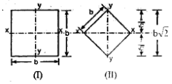
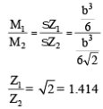
Calculated values show that arrangement (I) is 41.4% stronger than arrangement (II) for bending in the vertical plane shown. That is, the section modulus in (I) is larger by approximately 41.4% compared to (II).
Strongest rectangular beam cut from a circular log
Given a circular log of diameter D, find the rectangle of breadth b and depth d (d measured in the bending direction) that gives the maximum section modulus (hence maximum bending strength for given material).
The section modulus for a rectangle of breadth b and depth d about its neutral axis is Z = (b d^2) / 6 (for bending about the horizontal centroidal axis). For a given circular boundary the rectangle must fit inside the circle, so relationship between b and d follows from geometry (see).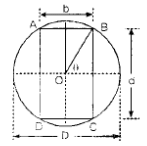 For maximum Z subject to b and d constrained by the circle, differentiation leads to the optimal ratio:
Hence the strongest rectangle that can be cut from a circle satisfies
b = d / √2
Geometrical and algebraic steps that lead to this result are shown in the following diagrams and expressions:
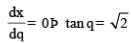


Therefore b = d / √2 gives the largest section modulus for a rectangular section inscribed in a circle of given diameter.
Comparing weights for sections of the same bending strength
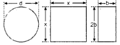
Problem statement (text preserved in content): Three beams have the same length, same allowable bending stress and are subjected to the same maximum bending moment. The cross section of the beams are a circle, a square and rectangle with depth twice the width. Find the ratio of the weights of the circular and rectangular beams with respect to the square beams.
Let the circular section be of diameter d.
Let the square section be of side x.
Let the rectangular section be of width b and depth 2b.
For equal bending moment under the same allowable stress, the section modulus must be equal for all three sections (M = σ Z and M, σ same for all). Therefore Z_circle = Z_square = Z_rectangle.
Using standard expressions for section modulus:
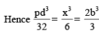
From these relations one obtains
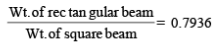
Numerical relationships derived give d = 1.193 x and b = 0.6299 x.
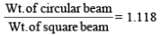
- Cross-sectional areas (which are proportional to weight for equal lengths and same material) then compare as: W_rectangular < W_square < W_circular.
Hence for the same bending strength under the same allowable stress, the rectangular section (depth twice width) is the lightest and the circular section is the heaviest.
Improving section modulus by trimming a square section
A square-section beam carrying a vertical bending moment can have its section modulus increased slightly by trimming off triangular corners (shaded portions in the figure) oriented parallel to the neutral axis. The geometry of the parts to be cut and the resulting increase in section modulus are shown in the diagrams:
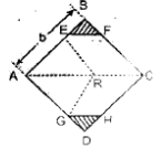
Key points:
- For maximum section modulus, the portion EB to be cut off satisfies the relation shown in
 .
. - The corresponding increase in section modulus is given in
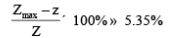 .
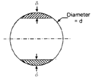
. - For a circular section a small increase in section modulus (about 0.7%) is possible by cutting segmental portions as shown, with the depth of the segment d approximately 0.011 times the diameter of the section.
Flitched Beams
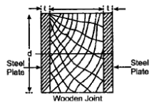
A flitched beam is a composite beam formed by placing steel plates (flitches) on a timber beam and fastening them together so that they act compositely. The composite action increases bending strength and stiffness. The steel and wood share bending stresses according to their stiffnesses.
The modular ratio (ratio of moduli of elasticity) is used to convert steel parts into equivalent wood width when analysing as an equivalent wooden section. The modular ratio is defined as:

Moment of resistance of the section
Case - 1: Flitches attached symmetrically at the sides.
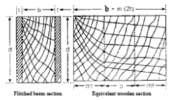
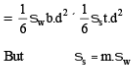
Consider a timber beam of breadth b and depth d with two identical steel plates each of thickness t attached symmetrically to the vertical sides. Let M_r be the total moment of resistance of the composite section. Let M_w and M_s be the moments of resistance contributed by the wood and steel respectively under the same curvature.
The steel contribution can be treated by transforming steel into an equivalent width of wood using the modular ratio m. The equivalent wooden section then has width b + m(2t) and depth d. Therefore the composite section's moment of resistance equals that of a wooden member of breadth b + m(2t) and depth d. This rectangular section is called the equivalent wooden section.
Case - 2: Flitches attached symmetrically at the top and bottom.
When flitches are attached at top and bottom, the steel plates are placed furthest from the neutral axis; this increases the section modulus more effectively than side flitches for the same steel area. Therefore top-and-bottom flitching usually gives higher moment carrying capacity than side flitching (for the same quantity of steel).
Beams Of Uniform Strength
For economy of material, a beam may be designed so that the extreme fibre stress is equal to the permissible stress at every section along its length. Such a beam is called a beam of uniform strength. Because bending moment varies along the span, the cross-section must vary accordingly. There are three common design approaches:
- Vary width while keeping depth constant.
- Vary depth while keeping width constant.
- Vary both width and depth.
Case 1 - Constant depth, varying width
Let permissible bending stress be σ. For any section at distance x from a reference (for example a support), bending moment is M(x). For a rectangular section of constant depth d and width b(x), the section modulus is Z = b(x) d^2 / 6. Requiring σ = M(x) / Z gives the width at x:
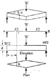
Therefore

and the width at mid-span (or any particular x of interest) can be obtained similarly, see  and
and  .
.
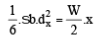
Case 2 - Constant width, varying depth
For constant width b, the required depth d(x) at a section with bending moment M(x) is obtained by equating M(x) = σ Z and using Z = b d(x)^2 / 6. Thus d(x) is proportional to √M(x). The detailed expressions and illustrative diagrams are shown below.

Applications, Remarks And Practical Notes
- The flexure formula σ = M y / I is the foundation for bending design in beams of many materials within the elastic limit.
- Section modulus Z = I / c is a convenient design parameter: for a given allowable stress and bending moment, choose a section with sufficient Z.
- Flitched beams are practical where combining timber and steel gives an economical solution: transform steel to equivalent timber using modular ratio for strength calculations.
- Beams of uniform strength are useful to save material; practical manufacturing and handling constraints may limit how much variation in cross-section is economical.
- When trimming sections to increase section modulus, the gains are often small and must be weighed against fabrication complexity and reduction in other properties (e.g., shear capacity).
Summary
The theory of pure bending leads to the flexure formula which relates bending stress to bending moment and section geometry. Section modulus is the primary geometric property used in bending design. Practical measures-such as choosing optimal orientation, cutting optimal rectangular sections from logs, adding flitches, or designing beams of uniform strength-allow more efficient use of material. All designs must respect the assumptions of simple bending and remain within elastic limits for the theory to be applicable.
FAQs on Bending Stresses in Beams
| 1. What are bending stresses in beams? |  |
| 2. How do bending stresses affect the performance of beams? | |
| 3. What factors influence the magnitude of bending stresses in beams? | |
| 4. How can bending stresses in beams be calculated or analyzed? | |
| 5. What are some common techniques to reduce bending stresses in beams? | |


