Shear Stresses in Beams

(ii) Solid Circular Section
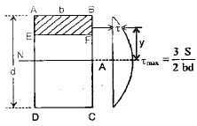
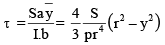
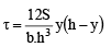
- The shear stress at a fibre on the plane of cross-section located at a distance y from the neutral axis is given by


The symbol Q denotes the first moment of the area above the fibre EF about the neutral axis. The quantity y is the distance from the neutral axis to the fibre under consideration. The symbol I is the second moment of area (moment of inertia) of the entire section about the neutral axis. The symbol b is the width of the section at the level EF (i.e., the breadth through the fibre where shear is being evaluated).
- Shear stress in terms of y from the neutral axis is given by

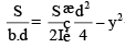
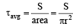
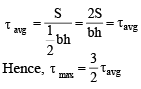
- Average shear stress across the section is given by

- Maximum shear stress occurs at the neutral axis and is given by

Hence

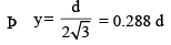
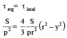
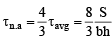
- The distance from the neutral axis at which the local shear stress equals the average shear stress is given by
(ii) Solid Circular Section
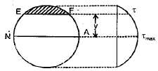
- The shear stress at a fibre on the plane of cross-section located at a distance y from the neutral axis is given by
- Maximum shear stress occurs at the neutral axis and is given by

- Average shear stress is given by
Hence

- The distance from the neutral axis at which the local shear stress is equal to the average shear stress is given by

(iii) Triangular Section
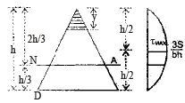
- The shear stress at a distance y from the vertex (or from the neutral axis as defined for the triangular section) is given by
- Maximum shear stress exists at(at the middle of the triangle) and is given by


- Average shear stress for the triangular section is given by
- Shear stress at the neutral axis:measured from the top is given by

(iv) Diamond Section
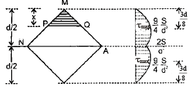
- Shear stress at level PQ is given by
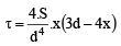
- Shear stress at the neutral axis is

- Average shear stress =

Hence tn.a. = tavg
- Maximum shear stress occurs atfrom top and bottom or
 from the neutral axis

Hence

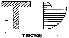
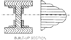
(V) I Section
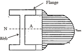
- Shear stress distribution in the flange is given by
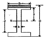
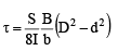
- Shear stress at the junction of flange and web, but within the flange, is

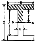
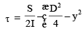
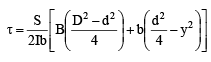
- Shear stress distribution within the web is
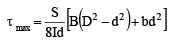
- Maximum shear stress exists at the neutral axis and is given by
- Shear stress at the junction of web and flange but within the web is
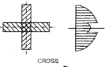
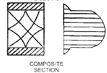
Shear stress distribution in some other sections:
Core Of Sections Of Different Shapes
1. Rectangular Section
For an eccentric axial load to produce no tensile stress anywhere in the cross-section, the eccentricity must be limited. The condition for no tension may be written as
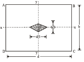
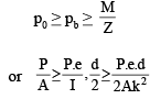

where k is the radius of gyration of the section with respect to the neutral axis and d is the depth of the section. Thus, for no tension in the section, the eccentricity must not exceed

For a rectangular section of width b and depth d,

and area A = b · d.
Hence

Substituting this value of k, we get

or

Thus the stress will be wholly compressive throughout the section if the line of action of the axial load lies within the rhombus (shaded in typical figures), the diagonals of which are of length d/3 and b/3 respectively. This rhombus is called the core or kern of the rectangular section.
2. Solid Circular Section
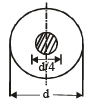
The core of a solid circular section is a circle, concentric with the section, of diameter d/4.
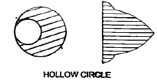
3. Hollow Circular Section
For a hollow circular section,

Hence the core for a hollow circular section is a concentric circle of diameter

where d is the inner diameter and D is the outer diameter of the hollow circular section.
Notes and explanatory remarks (method and key formula):
- The general formula used throughout for shear stress at a distance from the neutral axis isτ = VQ / (I b)where V is the shear force at the cross-section, Q is the first moment of the area above (or below) the fibre about the neutral axis, I is the second moment of area of the entire section about the neutral axis, and b is the width of the section at the level of the fibre.
- To find the shear distribution:Calculate Q for the area cut off by a line at distance y from the neutral axis.Substitute Q, I and b into τ = VQ/(I b) to obtain τ as a function of y.
- Average shear stress over the whole section is V/A, where A is the total cross-sectional area.
- Maximum shear stress for common sections:Use the derived τ(y) and evaluate at y = 0 (neutral axis) to obtain τmax. Typical results obtained by the method above are:Rectangular section: τmax = 3V / (2 b d) = (3/2) (V/A).Solid circular section: τmax = 4V / (3πR^2) = (4/3) (V/A), where R = d/2.
- The distance from the neutral axis where τ equals the average shear can be found by solving τ(y) = V/A for y.
- For non-standard shapes such as diamond, I-section and various built-up sections, evaluate Q and b carefully for each region (flange, web) and apply τ = VQ/(I b) piecewise. The placeholders above indicate the detailed expressions and diagrams for those shapes.
Applications and remarks for practice:
- Use shear stress distribution to check shear failure and to design web thickness in beams, especially in rolled and built-up sections.
- When calculating shear in thin webs, treat the web separately from the flanges and use the appropriate b (web thickness) in τ = VQ/(I b).
- Core (kern) checks are important for eccentrically loaded columns and short members to ensure no tensile stress develops in cross-section.
FAQs on Shear Stresses in Beams
| 1. What are shear stresses in beams? |  |
| 2. How are shear stresses distributed in a beam? | |
| 3. What factors affect the magnitude of shear stresses in beams? | |
| 4. How do shear stresses affect the structural integrity of beams? | |
| 5. How can shear stresses be reduced in beams? | |


