Springs


SPRINGS
- A spring is a device in which the material is arranged so that it can undergo a considerable elastic deformation and return to its original shape without permanent distortion.
- A spring is used to absorb and store mechanical energy due to resilience, and to release that energy when required.
- The quality of a spring is judged from the amount of energy it can absorb for a given allowable stress; the spring that absorbs the greatest energy for the given stress is considered the best.
Stiffness of a spring
Stiffness (also called spring rate) is the load required to produce a unit deflection in the spring. It is denoted by K and has units of force per unit length (for example, N mm⁻¹ or N m⁻¹).
Types of springs
Springs are commonly classified according to how they store energy (type of resilience) and by their form. Important categories for mechanical design are:
- Bending springs - springs that store energy by bending; typical example: leaf spring.
- Torsion (helical) springs - springs that store energy by twisting of rods or wires; typical example: helical spring (closed-coiled, open-coiled, closely-coiled).
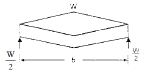
Leaf springs (bending springs)
Leaf springs are assemblies of slender plates (leaves) stacked and clamped together to form a spring that resists bending. They are widely used in vehicle suspension and other applications requiring load support with limited deflection.
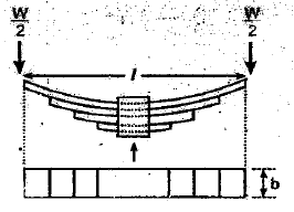
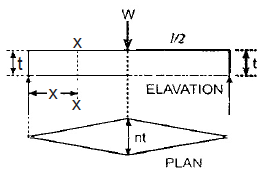
Common symbols used with leaf spring formulae:
- l = span of the spring (effective length)
- t = thickness of each plate (leaf)
- b = width of plates
- n = number of plates (leaves)
- W = load acting on the spring
- E = Young's modulus of the spring material
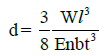
The central deflection and stress relations for leaf springs depend on the arrangement (equal-length leaves or graduated length), support conditions and loading. The detailed expressions and diagrams are provided in the image placeholders above.
Helical springs (torsion springs)
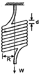
Closed-coiled helical spring subjected to axial loading
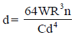
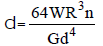
A closed-coiled helical spring is a rod (wire) wound into a helix where adjacent coils are close together. Under an axial load W, the wire of each coil undergoes torsion. For a circular wire of diameter d, mean coil radius R, number of active turns n and shear modulus G, the standard expressions used in design are:
- Deflection (axial) of the spring:δ = 8 W R³ n ÷ (G d⁴)
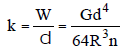
- Stiffness of the spring:K = G d⁴ ÷ (8 R³ n)
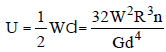
- Energy stored in the spring when deflected by δ under load W:U = 1/2 W δ = 1/2 K δ² = W² ÷ (2 K)
Closely coiled helical spring subjected to axial twist
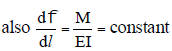
When a closely coiled helical spring is subjected to an axial twist (i.e., an applied torque or axial moment that tends to rotate the ends), each coil is bent/twisted and the spring experiences an angle of twist distributed along its length. The total angle of bend and the curvature distribution are constant along the wire for an ideal closely coiled spring; the detailed derivation and expressions are shown in the image placeholders below.
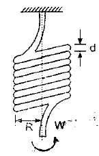
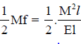
The total angle of bend is given in the figure and the change in curvature per unit length is constant; the corresponding stored energy expression for torsion is shown in the image placeholder.

Notation used in these expressions (as used in the images):
- R = mean radius of the spring coil
- n = number of turns (coils)
- M = applied moment or torque producing the twist
- I = second moment of area of the spring rod (wire) section
- E = Young's modulus
Open-coiled helical spring subjected to axial load
In an open-coiled helical spring (coils separated by pitch), an axial load produces both torsion in the wire and bending of the coils. Therefore the deflection is larger than for a closely coiled spring of the same geometry and wire size. The full expression for deflection includes contributions from torsion and bending and depends on pitch P, helix angle a, and the same basic geometric parameters (d, R, n). The required expressions are shown in the image placeholders below.
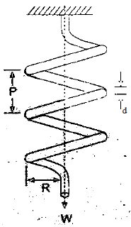
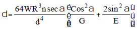
Where (as listed near the expressions):
- d = diameter of the spring wire
- R = mean radius of the spring coil
- P = pitch of the spring coil
- n = number of active turns of the coil
- G = modulus of rigidity (shear modulus)
- W = axial load on the spring
- a = angle of the helix
The image placeholders contain the full derivation and the final formulae for the open-coiled case. For practical design, closed-coiled formulae are often used when coils are closely spaced; corrections for bending are applied for larger pitches.
Springs in series and parallel
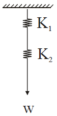
(i) Springs in series
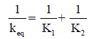
Two or more springs joined end-to-end are in series. For springs in series:
- The same load W acts through each spring.
- Total extension is the sum of individual extensions:δ = δ₁ + δ₂ + ⋯
- Equivalent stiffness K_eq is given by:1 ÷ K_eq = 1 ÷ K₁ + 1 ÷ K₂ + ⋯
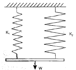
(ii) Springs in parallel
Two or more springs attached side-by-side share the load and have the same deflection; they are in parallel. For springs in parallel:
- Each spring has the same extension:δ = δ₁ = δ₂ = ⋯
- The applied load is shared by the springs:W = W₁ + W₂ + ⋯
- Equivalent stiffness is the sum of individual stiffnesses:K_eq = K₁ + K₂ + ⋯
Design notes, practical considerations and applications
- Material selection: Spring material should have suitable elastic limit, fatigue strength and resilience. Common materials include spring steels (high-carbon alloys), stainless steels and non-ferrous alloys for corrosion resistance.
- Stress concentration and Wahl correction: For helical springs, curvature of the wire introduces a stress concentration; a correction factor is applied to torsional shear stress in design (details in standard texts).
- Fatigue and endurance: Repeated loading reduces life; design must consider maximum shear stress under working and endurance limits.
- Buckling and stability: Long slender springs may buckle under compressive loads - shape and support must be arranged to avoid instability.
- Applications: Vehicle suspension (leaf springs), valve springs, shock absorbers, load-bearing mounts, measuring instruments (spring balances), and energy storage elements in mechanical devices.
Summary
Springs store elastic energy by bending or torsion. Their performance is measured by stiffness and the energy they can absorb. Leaf springs act by bending, while helical springs act primarily by torsion of the wire. Closed-coiled helical springs have standard formulae for deflection, stiffness and energy stored; open-coiled and closely coiled springs have additional effects (bending, pitch and helix angle) that modify the simple expressions. Equivalent stiffness for combined springs follows the same algebra as resistances in series/parallel: reciprocals add in series; stiffnesses add in parallel. The image placeholders included above contain derivations and specific formulae and should be used alongside these notes when performing calculations.
FAQs on Springs
| 1. What is mechanical engineering? |  |
| 2. What are the career options in mechanical engineering? | |
| 3. How long does it take to complete a degree in mechanical engineering? | |
| 4. What are the key skills required to succeed in mechanical engineering? | |
| 5. What are the future prospects of mechanical engineering? | |


