Pavement Design


Types of pavements
Pavements are classified by their structural behaviour into three principal types. Each type differs in the way it transmits wheel loads to the supporting layers and in the materials used.
Flexible pavements
Definition: Flexible pavements are those whose layers have negligible flexural strength and which distribute wheel loads by grain-to-grain action of granular materials. Surface deformities of lower layers are reflected on the pavement surface.
- Flexible pavements commonly use bituminous materials (bituminous concrete, open-graded mixes), granular aggregates (with or without bituminous binders), water-bound macadam (WBM) and soil-aggregate mixes.
- They are usually designed by empirical charts or equations; semi-empirical and theoretical methods are also used.

- Principal components:
- Soil subgrade
- Sub-base course
- Base course
- Surface (wearing) course
Rigid pavements
Definition: Rigid pavements are concrete slabs that possess significant flexural rigidity and transfer loads by slab (plate) action rather than grain-to-grain contact.
- Rigid pavements are made of Portland cement concrete - plain, reinforced or prestressed.
- They are analysed using elastic plate on elastic foundation theory; design commonly follows Westergaard's and related methods.
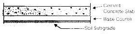
- Typical layers: cement concrete slab; base course; soil subgrade.
- Plain cement concrete slabs are expected to take up flexural stresses up to about 40 kg/cm².
Semirigid pavements
- Semirigid pavements use bound materials such as pozzolanic concrete, lean cement concrete or soil-cement which provide appreciable stiffness but limited flexural resistance compared with rigid pavements.
- These layers have low resistance to impact and abrasion and are usually used below a flexible wearing course.
Functions of pavement components
Soil subgrade
The subgrade ultimately supports the pavement load. The top 50 cm of subgrade should be properly compacted at the Optimum Moisture Content (OMC) to achieve required strength and to avoid overstressing the soil.
- Common tests for evaluation:
- California Bearing Ratio (CBR) test
- California Resistance Value test (Stabilometer / Cohesionmeter related tests)
- Triaxial compression test
- Plate bearing test
Sub-base and base course
- These layers are usually composed of broken stone aggregates. Graded smaller-sized aggregates are preferable at the sub-base rather than large boulders.
- Under flexible pavements, base and sub-base improve load-supporting capacity by distributing loads through a finite thickness.
- Under rigid pavements, base courses prevent pumping and protect the subgrade against frost action.
Wearing (surface) course
- The wearing course provides a smooth riding surface, resists tyre pressures, resists abrasion and provides water-tightness.
- Stability of bituminous wearing courses is estimated by the Marshall stability test which helps determine the optimum bitumen content using parameters such as stability, density, voids in mineral aggregate (VMA) and voids filled with bitumen (VFB).
- Plate bearing and Benkelman beam tests are also used to assess wearing course and overall pavement performance.
Design factors for flexible pavements
Key factors to consider when designing flexible pavements include:
- Design wheel load
- Subgrade soil characteristics
- Climatic factors (temperature, rainfall, frost)
- Pavement component materials
- Environmental and site factors (drainage, groundwater, seasonal moisture)
Design wheel load
Important wheel-load related parameters are explained below.
Maximum wheel load
- IRC specifies a maximum legal axle load of 8170 kg with a maximum equivalent single wheel load of 4085 kg.
- Total wheel load influences the choice and thickness of pavement layers, particularly the surface course quality.
- Vertical stress under a circular load is commonly computed using Boussinesq's theory.
Contact pressure
- Tyre (inflation) pressure and the area of contact affect stresses in the upper pavement layers; higher tyre pressures demand better quality materials in the top layers.
- Contact area is often assumed circular, but in practice it can be elliptical.
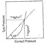
- When tyre pressure is less than 7 kg/cm² the contact pressure is generally greater than tyre pressure; when tyre pressure exceeds 7 kg/cm² the contact pressure is lower than tyre pressure.
- Rigidity factor (R.F.) = Contact pressure / Tyre pressure.
- For example, if contact pressure = 7 kg/cm² and tyre pressure = 7 kg/cm² then R.F. = 1. If tyre pressure < 7 kg/cm² then R.F. > 1; if tyre pressure > 7 kg/cm² then R.F. < 1.
- R.F. depends on the tension developed in tyre walls and the tyre construction.
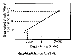
Equivalent single wheel load (ESWL)
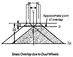
- The stress effect at depth beneath a dual wheel assembly is neither equal to one wheel nor exactly twice a single wheel. ESWL is the single wheel load that produces the same maximum stress at a given depth as the dual wheel assembly.
- Load dispersion is often considered at 45°. If d is the clear gap between two wheels, a is the radius of contact area of each wheel and S = d + 2a is the spacing between wheel centres, then separate or overlapping stress zones are considered depending on depth relative to d/2 and 2S.
- ESWL may be determined graphically using log-log plots; representative points for single and dual loads are plotted to find the locus of equivalent loads.
Repetition of loads
- Pavement response depends on the number of load repetitions as well as magnitude.
- If a pavement fails after N₁ repetitions of load P₁ and also fails after N₂ repetitions of load P₂, then P₁N₁ and P₂N₂ are treated as equivalent damage terms.
- Empirical observations indicate that a pavement thickness required for 10⁶ repetitions is larger; thickness required for failure under a single repetition is roughly t/4 (an empirical relation used in some methods).
Elastic moduli of pavement materials
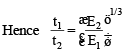
- Elastic modulus (Young's modulus) of pavement materials may be estimated by plate bearing tests. For a flexible plate, maximum vertical deflection Δ under pressure p relates to elastic modulus E of the material.

If a rigid circular plate is used instead of a flexible plate, the corresponding relation differs and is represented by the next diagram/formula.

- In the formulas, a is plate radius, p is applied pressure and Es is the Young's modulus of the pavement material.
Frost action
- Frost action denotes damage due to frost-heave caused by freezing of pore water. Capillary supply of water and subfreezing temperatures produce ice lenses that cause heave; non-uniform heave and thaw settlements damage pavement geometry.
- Factors increasing frost risk: frost-susceptible soils, subfreezing temperatures, ready water supply by capillarity, and insufficient cover over frost-susceptible layers.
- Mitigation measures: good surface and subsurface drainage, capillary cutoffs, soil stabilisation or providing non-frost-susceptible fill.
Design of flexible pavements - approaches and methods
Design approaches are grouped into three broad categories.
- Empirical methods: Based on field experience and correlations with soil physical parameters. Examples: Group Index method, CBR method, Stabilometer method, McLeod method.
- Semi-empirical / semi-theoretical methods: Based on stress-strain relationships supplemented by experience (e.g., triaxial test based methods).
- Theoretical methods: Based on mathematical models of layered elastic systems (e.g., Burmister's multilayer elastic theory).
Group Index (G.I.) method
- G.I. is an empirical parameter; higher G.I. indicates weaker subgrade and hence greater pavement thickness for a given traffic volume.
| Subgrade | Group index value |
|---|---|
| Good | 0-1 |
| Fair | 2-4 |
| Poor | 5-9 |
| Very poor | 10-20 |
- Traffic classification used with G.I. charts: Light < 50 vehicles/day; Medium 50-300 vehicles/day; Heavy > 300 vehicles/day.
- G.I. is correlated with required pavement thickness through design charts.
- Limitation: this method emphasises only subgrade soil physical properties and does not explicitly consider the strength of individual pavement component materials.
California Bearing Ratio (CBR) method
- CBR is an empirical method widely used because of its simplicity; CBR test results are correlated with required pavement thickness.
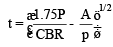
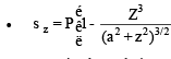
The displayed expression is applicable when the CBR value of the subgrade is less than 12%.
- Symbols: t = pavement thickness (cm); P = wheel load (kg); CBR = California Bearing Ratio (%); A = contact area (cm²).
- CBR method relates the subgrade strength (CBR) and traffic loading to total pavement thickness above the subgrade.
IRC recommendations for CBR use
- Perform CBR tests on remoulded laboratory samples; in-situ test results are not recommended for design.
- Compact soil samples at OMC to Proctor density for testing.
- Soak test samples for 4 days before testing unless the site is in a dry zone (< 50 cm annual rainfall).
- Test at least three samples for each soil type at the same density and moisture. If variation exceeds permissible limits, average six samples.
| Permissible variation | CBR % |
|---|---|
| ±3% | up to 10% |
| ±6% | 10-30% |
| ±10% | 30-60% |
- The top 50 cm of subgrade should be compacted to at least 95-100% Proctor density.
- To estimate future heavy vehicle numbers considering growth rate, IRC suggests:
A = P [1 + r]^(n + 10)
where A = number of heavy vehicles/day for design (weight > 3 tonnes), P = number of heavy vehicles/day at last count, r = annual growth rate, n = years between the last count and year of construction completion. - For rural roads, P may be a seven-day average and r may be taken as 7.5% where appropriate.
- Design thickness values are for single axle loads up to 8200 kg and tandem axle loads up to 14500 kg; for higher axle loads thickness must be increased accordingly.
- When subbase contains aggregates above 20 mm, the measured CBR of that material may not be valid for design of layers above it.
- Limitation: The CBR method gives total pavement thickness above the subgrade but does not distribute the thickness among component layers; selection of component materials must therefore be done carefully for durability and economy.
California Resistance Value method
Total pavement thickness is given by the empirically derived expression shown below.
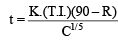
- In the expression: K = numerical constant (0.166), T.I. = Traffic Index = 1.35 (EWL)^0.11, R = Stabilometer resistance value, C = Cohesionmeter value.
- Equivalent C value for composite layers is calculated by:

- where t₁ and t₂ are the thicknesses of two pavement layers and C₁ and C₂ their corresponding Cohesionmeter values.
| Material | C Value |
|---|---|
| Soil-cement base course | 120-130 |
| Bituminous concrete | 60-62 |
| Open-graded bituminous mix | 22-30 |
| Gravel base course | 15 |
- The annual EWL (equivalent wheel loads) is the accumulated sum of the products of axle load constants and the number of axle loads.
Tri-axial (Triaxial) method
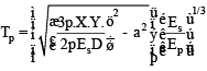
- Pavement thickness Tₛ for a layer with modulus Eₛ is obtained from empirical/semi-empirical expressions derived from triaxial and plate load test correlations.
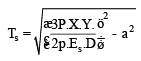
- Traffic coefficient X takes values based on Average Daily Traffic (ADT): X = 1/2 for ADT = 40-400; X = 1 for ADT = 401-1200; X = 2 for ADT = 1201-1800; higher ADT values use larger X (table values chosen by method).
- Rainfall coefficient Y may be Y = 0.5 for average annual rainfall 38-50 cm and Y = 1.0 for 101-127 cm (method dependent).
- The pavement and subgrade are considered a two-layer system so a stiffness factor is introduced to account for differing elastic moduli of the layers.
McLeod method
- This empirical method is based on plate load test results and recommends an equation of the form shown below for gravel base thickness:

- Symbols: T = required thickness of gravel base (cm); P = gross wheel load (kg); S = total subgrade support (kg) for the same contact area, deflection and repetition of load P; K = base course constant.
- Subgrade support S is calculated from measured or calculated support for a standard deflection (for example 30 cm deflection over a specified number of repetitions) as required by the method.
Burmister's layered elastic method
- Burmister's method treats the pavement as a system of horizontal, isotropic, homogeneous, elastic layers with the top layer having the highest modulus of elasticity and each layer acting continuously over the other.
Assumptions:
- Materials in each layer are isotropic, homogeneous and linearly elastic.
- Layers are infinite horizontally and of finite thickness vertically (top layer is finite thickness, underlying layers are modelled as semi-infinite where appropriate).
- Layers are in continuous contact; the top layer is free of external shear and normal stresses outside the loaded area.

- A stiffness (reinforcing) factor involving Ep (pavement modulus) and Es (subgrade modulus) is used in layered computations to capture the beneficial reinforcing action of stiffer surface layers.
Design of rigid pavements
- Rigid (cement concrete) pavements carry loads primarily by flexural rigidity of the slab. Design addresses slab bending under wheel loads, temperature effects and edge support conditions.
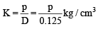
- Westergaard's analysis uses a rigid circular plate (75 cm diameter) to determine the modulus of subgrade reaction K for design calculations.
Relative stiffness of slab to subgrade
- Relative stiffness determines slab deflection under load. The radius of relative stiffness is a parameter combining slab stiffness, thickness and subgrade reaction.
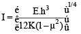
In the notation, E = modulus of elasticity of concrete (kg/cm²), μ = Poisson's ratio for concrete (typically ≈ 0.15), h = slab thickness (cm), K = modulus of subgrade reaction (kg/cm³).
Stresses in rigid pavement
Principal stresses to consider:
- Wheel (load) stresses
- Temperature stresses - which include warping stresses and frictional stresses
Critical load positions are identified as:
- Interior loading - load applied away from edges and corners
- Edge loading - load applied near but not at a corner
- Corner loading - load applied near a corner where two edges meet
Temperature stresses
- Westergaard analysed temperature effects; they produce warping stresses due to differential temperature through the slab thickness and frictional stresses due to restraint between slab and foundation.
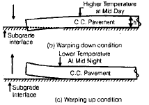
Warping stresses
- Daily and seasonal temperature changes cause slab warping. Maximum temperature difference often occurs in the evening; warping stresses are generally largest at interior regions and smaller towards corners.
- When slab warps downward (day heating) tensile stresses are induced at the bottom fibre; when slab warps upward (night cooling) tensile stresses occur at the top fibre.
- Warping stresses can be calculated by methods such as Bradbury's expression referenced in design codes.
Critical stress combinations
- During summer (mid-day), the most critical condition often occurs at the edge where load stress combines with warping and frictional stresses: critical = load stress + warping stress - frictional stress (first two are tensile; frictional is compressive).
- During winter (mid-day) the critical combination can occur at the bottom fibre where frictional stresses may be tensile due to contraction; critical = load stress + warping stress + frictional stress.
- At corners, where frictional restraint is minimal, critical combination is usually load stress + warping stress acting on the top fibre when the slab warps downward.
- Under identical conditions, edge combinations often produce higher critical stresses than corner combinations.
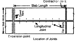
Design of joints in cement concrete pavements
Joints accommodate slab movements due to temperature, shrinkage and warping, and they distribute load across adjacent slabs. Joints are classified as transverse and longitudinal.
Transverse joints
Transverse joints are of the following types:
- Expansion joint
- Contraction joint
- Warping (hinged) joint
- Construction joint
Expansion joints
- Provided to allow slab expansion due to temperature rise and to permit contraction as well.
- Typical gap width is approximately 20-25 mm.
- Joint material (compressible filler) is often assumed to compress up to 50% of its thickness; hence expansion gap is designed considering the allowable concrete expansion.

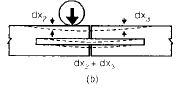
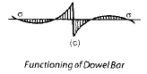
- Dowel bars are used to transfer load across transverse joints while allowing longitudinal movement. IRC recommends 2.5 cm diameter dowel bars of length 50 cm.
- Recommended spacing of dowel bars: 20 cm spacing for 15 cm thick slabs, 30 cm spacing for 20 cm thick slabs for a design load of 5100 kg.
Spacing of expansion joints
- For smooth interfaces laid in winter, spacing of expansion joints is typically 50-60 m; for smooth interfaces laid in summer, spacing is 90-120 m.
- For rough interfaces, spacing between expansion joints should not exceed 140 m (IRC guidance).
If δ′ is the allowable expansion in cm and δ¹ is half the joint width, the spacing of expansion joints Lₑ (m) may be calculated from the relation shown below.


Contraction joints
- Provided to permit slab contraction (shrinkage, temperature contraction). Contraction joints are spaced closer than expansion joints.
- IRC guidance: maximum spacing of contraction joints in reinforced concrete slabs is about 4.5 m; in plain reinforced slabs of thickness 20 cm the spacing may be up to about 14 m depending on details.
Warping (hinged) joints
- Warping joints relieve stresses due to warping and are commonly provided as longitudinal joints with tie bars acting as hinges.
- These are rarely needed if expansion and contraction joints are properly designed and provided.
Longitudinal joints
- Provided when pavement width exceeds about 4.5 m to accommodate differential shrinkage and moisture variation between centre and edges, which can cause longitudinal cracking at the centre.
- Longitudinal joints act as hinges to keep adjacent slabs at the same level; tie bars are used to hold slabs together across the joint.
- IRC recommends plain butt joints with tie bars where required.
Joint filler and sealers
Joint filler
- Desirable properties: compressibility, elasticity and durability.
- Common types: soft wood, bitumen-impregnated fibre board, cork bound with bitumen.
- IRC specifies typical bitumen content in impregnated filler as about 35%.
Joint sealer
- Desirable properties: adhesion to concrete edges, extensibility without fracture, resistance to ingress of grit and water, and durability.
- Higher viscosity bitumens and rubber-bitumen compounds are commonly used; air-blown bitumen offers reduced temperature susceptibility.
Final notes
- The material above summarises the key concepts, parameters and commonly used empirical and theoretical design methods for flexible and rigid pavements.
- Design codes (for example IRC recommendations) and local site investigations (soil properties, traffic surveys, climatic data) must be followed for actual pavement design. Laboratory tests such as CBR, plate bearing, triaxial tests and field observations form the basis of reliable designs.
FAQs on Pavement Design
| 1. What factors are considered in the design of pavement in civil engineering? |  |
| 2. How is the traffic volume determined for pavement design? | |
| 3. What are the different types of pavement layers used in civil engineering? | |
| 4. How do soil conditions affect pavement design? | |
| 5. What is the expected service life of a pavement? | |


