Polyphase Induction Machine


Introduction
- Polyphase induction motor is a singly-excited alternating-current machine: the stator is directly connected to an AC source while the rotor receives energy from the stator by electromagnetic induction.
- Balanced polyphase currents in a distributed polyphase stator winding produce a rotating magnetomotive-force (m.m.f.) wave of nearly constant amplitude. The stator and rotor m.m.f. waves combine to give a resultant air-gap flux density wave which rotates at synchronous speed when observed in the stationary frame of the stator.
- Since the rotor cannot run at synchronous speed under normal motoring conditions, the induction motor is also called an asynchronous machine.
Constructional Features
Stator
- The stator comprises the stator frame, stator core (laminated steel stack), distributed polyphase winding (usually three-phase), two end covers and bearings.
- The stator core is formed from cylindrical steel laminations with slots on the inner periphery to accommodate the stator conductors; the winding is usually distributed and can be connected in star or delta.
- Three coils labelled a-a', b-b' and c-c' (for a three-phase machine) are space-displaced by 120° electrical around the stator periphery.
- The stator winding is distributed to reduce harmonic m.m.f. and to obtain a more sinusoidal air-gap flux. The air gap between stator and rotor should be as small as practicable to reduce leakage flux and to improve the operating power factor and torque per ampere.


Rotor
- There are two common rotor types used in polyphase induction motors: squirrel-cage rotor and wound rotor (slip-ring rotor).
Squirrel-cage rotor
- Rotor slots contain uninsulated copper or aluminium bars which are short-circuited by end rings of the same material; bars and end rings are joined by welding, brazing or riveting.
- There is no means to insert external resistance into the rotor circuit of a squirrel-cage induction motor (SCIM).
- Rotor slots are usually skewed to minimise cogging and provide smooth, quiet running.

Wound rotor (slip-ring rotor)
- The rotor carries a distributed winding, usually connected in star; the three phase leads are taken out to three slip rings mounted on the shaft and insulated from it.
- External resistances may be inserted in series with the rotor winding via brushes and slip rings to control starting torque and speed (useful for wide-range speed control in starting and low-speed operation).
- Wound-rotor machines are used when external rotor resistance is required for speed control or when high starting torque is needed.
Induction Motor As A Transformer
- An induction motor resembles a transformer in several respects: two windings (stator and rotor) magnetically coupled through the air gap, leakage reactances and winding resistances, induced emf when flux links conductors and energy transfer by electromagnetic induction.
- If the rotor winding is open-circuited and the rotor is prevented from turning (standstill), a wound-rotor induction motor (WRIM) behaves like a transformer at no load: induced emfs of the same frequency as the stator supply are produced in rotor and stator.
- When balanced three-phase stator voltages of frequency f1 are applied, a rotating flux of synchronous speed is produced. This flux links stator and rotor windings and induces per-phase emfs.

N1 = stator series turns per phase; k w1 = stator winding factor.
- Per-phase induced emf in standstill rotor winding is proportional to rotor turns N2 and rotor winding factor k w2.

N2 = rotor series turns per phase; k w2 = rotor winding factor.
- The emf (voltage) ratio between stator and rotor is analogous to the turns ratio of a transformer when referred appropriately to the same speed and flux conditions.

- A wound-rotor induction machine at standstill is similar to a transformer at no-load; a three-phase induction motor with a blocked rotor corresponds to the short-circuit test of a transformer; and both stator and rotor have leakage reactances and resistances analogous to transformer leakage and winding resistances.
Major differences between induction motor and transformer
- In an induction motor the stator winding is distributed along the air-gap periphery and requires a winding factor; in a transformer the windings are more concentrated and the core flux circulates through low reluctance iron, making the no-load reactive conditions different.
- No-load current in an induction motor is typically large (30-50% of full-load current) because mutual flux must cross the air gap; in a transformer no-load current is small (2-6% of full-load) since mutual flux remains confined largely to the iron core.
Rotating Magnetic Field
- Balanced three-phase currents in three identical stator winding sets displaced by 120° electrical in space produce three time-varying m.m.f. waves which sum to form a rotating m.m.f. (travelling wave) of constant amplitude and rotating at synchronous speed.
- For a P-pole machine, the synchronous speed in electrical radians is ω = 2πf and in mechanical revolutions per minute is Ns = 120 f / P.

- The three phase currents Ia, Ib, Ic set up three pulsating m.m.f. components Fa, Fb, Fc directed along the magnetic axes of phases a, b and c. Their phasor sum is a travelling mmf wave of amplitude (3/2) Fm.

- The travelling mmf wave moves around the air gap circumference at synchronous speed; reversing the phase sequence (interchanging any two supply leads) reverses the direction of rotation of the magnetic field.


- Magnetic field rotates at speed Ns with respect to the stator winding.
Principle Of Operation
- The rotating stator field cuts the rotor conductors inducing an emf and hence current when the rotor circuit is closed (squirrel cage) or when slip rings supply brush contacts (wound rotor).
- By Lenz's law the induced rotor currents produce magnetic fields that oppose their cause; the interaction of rotor currents and stator rotating field produces a torque that tends to drive the rotor in the direction of the rotating field, causing the rotor to accelerate until steady-state speed Nr slightly less than synchronous speed Ns.
- If the rotor were to turn exactly at synchronous speed there would be no relative motion between field and rotor conductors, hence no induced emf, no rotor current and no torque - therefore rotor speed must be less than Ns in motoring mode.
Rotor Frequency, Slip And Relationships
- When the rotor is stationary, the rotating air-gap flux cuts the rotor conductors at synchronous speed Ns, so the rotor emf and current frequency f2 equals the stator (supply) frequency f1.
- When the rotor turns at speed Nr (rps), the relative speed between the stator field (rotating at Ns) and the rotor conductors is (Ns - Nr) rps. The induced rotor frequency is reduced accordingly.


- Slip s is defined as the fractional speed difference between synchronous and rotor speeds: s = (Ns - Nr) / Ns.
- Rotor frequency is f2 = s f1. For this reason f2 is called the slip frequency.


Rotor Power: Air-gap Power, Developed Power, Shaft Power
- Per-phase input to the rotor (air-gap power per phase) can be written as Pg = E2 I2 cos θ2, where E2 and I2 are phasor magnitudes of induced emf and rotor current and θ2 the corresponding phase angle.

- The mechanical power developed (air-gap mechanical power) minus mechanical losses gives the output shaft power. Power transferred across the air gap (Pg × number of phases) minus rotor copper loss equals developed mechanical power which, after subtracting friction and windage and core losses, yields shaft power.

Pg = stator power input - stator I2R losses - stator core loss (per phase accounting as required).
Losses And Efficiency
Fixed losses
- Fixed losses are those that are nearly constant with load: core loss (hysteresis + eddy), bearing friction loss, brush friction loss (in WRIM only), and windage loss.
Variable losses
- Variable losses increase with load and include stator copper (I2R) loss, rotor copper loss, brush contact loss (WRIM), and stray load losses.

Power flow diagram for a three-phase induction motor:

Where Psh = shaft power; Pf = fixed losses = core loss + friction and windage; Poh = stator and rotor copper losses + brush contact loss (if any).
Analysis Of The Equivalent Circuit

- The standard per-phase equivalent circuit (referred to the stator) models stator resistance r1, stator leakage reactance x1, magnetising reactance Xm, and the rotor leakage and rotor resistance referred to stator. Core loss resistance Rc is often neglected in simple diagrams but its effect must be accounted for when calculating no-load losses.
- Steady-state performance quantities such as stator current, torque, speed and losses can be computed from this equivalent circuit.

- Zf denotes the per-phase impedance offered to the stator by the rotating air-gap field; it includes the reflected rotor leakage impedance and the magnetising reactance Xm.

Impedance seen by the stator applied voltage V1:
Z1 = r1 + j x1 + Zf
- Stator current I1 = V1 / Z1.
- Per-phase air-gap power can be obtained from the equivalent circuit quantities and the rotor referred power expression.

Torque-slip Characteristics
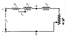
- Using Thevenin's theorem, the portion of the circuit containing r1, x1, Xm and the supply can be reduced to an equivalent Thevenin voltage Ve and impedance Ze seen by the rotor circuit. This simplifies torque and current calculations.
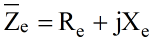
Where Ve and Ze are given by the usual Thevenin relations for the open-circuit and short-circuit impedances.


- For most practical induction motors Xm is large compared to r1 and so simplifications are sometimes applied: (x1 + Xm) ≫ r1.


Here X1 = x1 + Xm is the stator self-reactance per phase (including magnetising reactance as appropriate).
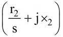
- Rotor current (referred to stator) can be expressed in terms of the Thevenin voltage Ve, the equivalent impedance and the rotor resistance r'2/s and leakage reactance x'2.

- Total electromagnetic torque can be derived from the air-gap power and rotor speed; m denotes the number of stator phases (usually m = 3).

Here m is the number of stator phases.

where

- Depending on slip s, the induction motor operates in different modes: motoring (0 < s="" ≤="" 1),="" generating="" (s="" />< 0)="" and="" braking/plugging="" (s="" /> 1).

Motoring mode (0 < s ≤ 1)
- Rotor rotates in the same direction as the stator field; slip varies from 1 at standstill to nearly zero at synchronous speed.
Generating mode (s < 0)
- A machine acts as an induction generator when its rotor is driven above synchronous speed while the terminals are connected to a constant-frequency voltage source; negative slip implies power is delivered back to the supply.
- If the stator is disconnected from the supply and the rotor is driven above synchronous speed, no generating action occurs because the stator quantities are not kept at the required terminal conditions.
Braking (plugging) mode (s > 1)
- Plugging is obtained by reversing the phase sequence (interchanging two stator supply leads) while the rotor is still turning in the original direction; this produces an electromagnetic torque opposite to the rotor motion, rapidly bringing the rotor to rest.
- During plugging the slip exceeds unity and mechanical power can be returned to the supply (with negative Pm), but heavy thermal stress occurs and the stator must usually be disconnected before reversing the motor to the opposite direction.
Maximum (Breakdown) Torque
- The maximum internal torque (also called stalling torque, pull-out or breakdown torque) occurs when the power absorbed in the rotor circuit r'2/s is maximised. This happens when the magnitude of rotor branch impedance equals the magnitude of the source-seen impedance.
- The slip smT at which maximum torque occurs is proportional to the rotor resistance r'2, while the magnitude of maximum torque is independent of r'2 (for fixed applied voltage and reactances).
- Increasing rotor resistance shifts the torque-slip curve so that maximum torque occurs at larger slip (lower speed) but the peak torque value remains essentially unchanged. This property is exploited in wound-rotor motors to improve starting performance.

where X = x'2 + Xe (as per equivalent circuit notation).


- The slip at which maximum torque occurs increases with rotor resistance; therefore inserting external rotor resistance raises starting torque at the expense of increased rotor losses.

Induction motor torque-slip curves for different rotor-circuit resistances.
- Observations: maximum torque is proportional to the square of stator voltage; increasing stator resistance or leakage reactance reduces torque; keeping air gap small increases mutual flux and hence torque.
- Starting torque and starting current, as well as power factor during starting, are affected by rotor circuit resistance.
Starting Torque
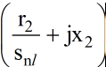
- Starting torque depends on rotor resistance and reactances; to obtain maximum starting torque the rotor circuit resistance should be increased appropriately (external resistance in a WRIM) so that the impedance condition for maximum power transfer is met at s = 1.

- To obtain the required starting performance in a wound-rotor motor an external resistance equal to a specified fraction of the rotor per-phase resistance is inserted during starting and removed as the motor accelerates.


Motor Operation Near Synchronous Speed
- When slip s is small, the term r'2/s becomes large; rotor current and torque expressions must be evaluated accordingly from the equivalent circuit.

Motor Torque In Terms Of Tem

Neglecting small stator resistances where appropriate leads to simplified torque expressions used for analysis near synchronous speed and for approximate design calculations.

By substituting the condition for maximum torque into the torque expression one obtains the standard formulae for smT and Tem,max.


Power-slip Characteristics
- The internal mechanical power developed depends on slip and rotor resistance; there is a slip at which the developed mechanical power is maximum, and this maximum power depends on rotor resistance unlike the torque maximum.


- At starting (s = 1) all power crossing the air gap appears as rotor I2R loss so developed mechanical power is zero; as slip reduces, some rotor I2R becomes available as mechanical power. During plugging, power can be returned to the supply (negative Pm).

- To get maximum power output from an induction generator driven above synchronous speed the rotor must be driven to an appropriate speed (corresponding negative slip magnitude).


Equivalent Circuit Parameters - Tests
The equivalent circuit parameters of an induction motor are determined from two basic tests: the no-load (running light) test and the blocked-rotor (short-circuit) test.
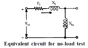
No-load (running light) test
- Run the motor at rated voltage and frequency with no mechanical load. Measure per-phase applied voltage Vnl, input current Inl and input power Pnl. The no-load slip is very small so the rotor branch impedance r'2/s is very large and can be neglected when finding magnetising reactance.
- The terminals reflect a no-load reactance Xnl ≈ x1 + Xm = X1. From Vnl, Inl and Pnl the magnetising reactance Xm and rotational losses (friction, windage and core loss) can be estimated.

- Rotational losses Pr (friction + windage) and core losses are commonly found from the no-load test by subtracting stator copper loss at no-load from measured input power (accounting per phase and number of phases).

m is the number of stator phases (usually 3) and r1 is the per-phase stator resistance.
Blocked-rotor (short-circuit) test
- Lock the rotor and apply reduced balanced three-phase voltages to the stator (through a variac) until rated current flows; record per-phase applied voltage Vbr, current Ibr (rated) and input power Pbr.
- Choose the rotor position during the test so that measured current is the mean of its extreme values. Measure stator d.c. resistance per phase immediately after the test and multiply by a factor (1.1-1.3) to obtain the effective r1 at running temperature.
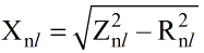
- The blocked-rotor impedance per phase is Zbr = Vbr / Ibr. From Pbr the per-phase resistance component can be obtained and hence the blocked-rotor reactance Xbr determined: Xbr = √(Zbr2 - Rbr2).


- Typically Xm ≫ rotor leakage reactance, so Xbr ≈ x1 + x'2. For wound-rotor machines one often assumes x1 ≈ x'2 ≈ ½Xbr, from which the separate leakage reactances can be allocated.
- Once x1 (or total leakage reactance) is determined, other parameters such as Xm, r'2 (per phase rotor resistance referred to stator) can be determined from the measured test data and appropriate formulae.


- Useful reminders: friction and windage losses can be computed from the no-load test; rotor core loss is usually negligible under normal running because rotor frequency (s f) is small when slip is small; the power input at no-load supplies stator copper loss, core loss and friction + windage.
- The d.c. resistance of stator winding is measured and multiplied by the appropriate factor (1.1-1.3) to estimate effective r1 under operating temperature.

Starting Of Three-phase Induction Motors
- A three-phase induction motor has a finite positive starting torque and is self-starting. However, starting current at full line voltage can be 5-7 times the full-load current for SCIMs. To limit starting current and avoid excessive voltage dips on the supply, several reduced-voltage starting methods are used.
Direct-on-line (across-the-line) starting
- The motor is connected directly to the supply at rated voltage; starting current is large but of short duration. This is acceptable if the supply has adequate short-circuit capacity and other equipment is not adversely affected by voltage dips.
- If Ist is the per-phase starting current and Ifl the full-load current, the ratio depends on motor design and impedance at standstill.


- The short-circuit standstill current per phase can be approximated by Isc = V1 / Zsc, where Zsc is the standstill per-phase leakage impedance referred to stator.


Stator resistor or reactor starting
- A resistor or series reactor is inserted in the stator circuit so that only a fraction x of line voltage appears across the motor during starting; this reduces starting current and starting torque by appropriate factors. The series element is cut out as the motor accelerates.


Autotransformer starting
- An autotransformer supplies a reduced voltage xV1 to the motor during starting. After acceleration the autotransformer is switched out and full line voltage is applied.
- Per-phase starting current drawn from the supply is reduced more than the motor current because of the autotransformer action; motor starting current scales with x while supply current scales with x2 under ideal no-load autotransformer assumptions.


- Remember: in autotransformer starting both starting current and starting torque are reduced by the same voltage factor.
Star-delta starting
- Motors designed for normal operation in delta may be started in star (Y) to reduce line voltage across each phase to 1/√3 of line voltage, thereby reducing starting current drawn from the mains to roughly one third of direct-delta starting current. After acceleration the winding is reconnected to delta.
- Star-delta starting also reduces starting torque approximately to one third of direct-delta starting torque, making this method suitable only where reduced starting torque is acceptable.


Speed Control Of Induction Motors
- Rotor speed is given by N = Ns(1 - s) where Ns = 120 f / P. Speed can therefore be varied by changing supply frequency f, changing the number of poles P (pole-changing), or varying slip s (by changing rotor resistance for WRIM or by external control).

Thus practical methods of speed control are: V/f control (variable frequency drives), pole changing (discrete speeds), rotor resistance control (WRIM), and cascade or slip-power recovery schemes for wide range control.

Reducing stator voltage reduces torque roughly proportional to V2, so voltage reduction is not a good wide-range speed control method.


For small slip approximations see the equivalent expressions obtained from the equivalent circuit.

To maintain the same full-load torque when slip changes it is necessary to adjust voltage appropriately; this leads to constraints on speed control by voltage variation alone.

Examples in the equivalent circuit show that reducing voltage to decrease speed increases currents and losses - limited speed-control range using stator voltage only.
Rotor resistance control (SRIM)
- Inserting external resistance in the rotor circuit of a wound-rotor induction motor increases slip for a given torque, enabling wide-range low-speed control. The disadvantage is that the slip power is dissipated in the external resistor, reducing efficiency. When slip-power recovery (feeding slip power back to supply) is used, overall efficiency improves.

Frequency control and V/f control
- Variable frequency drives (VFDs) change supply frequency f and keep the voltage V proportionally scaled so that V/f remains approximately constant; this maintains magnetising flux approximately constant and gives good torque capability over a wide speed range.
- At low frequencies the effects of stator impedance and rotor reactance must be considered to maintain torque and stability; modern VFDs manage pulse patterns to approximate sinusoidal supply and maintain V/f profiles.


V/f control illustrations


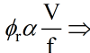
Keeping V/f constant maintains magnetising flux constant and preserves torque capability.

Nominal voltage V0 at rated nominal frequency f0 is the reference for V/f scaling.


Cogging
- Cogging (teeth-locking) is the magnetic locking between stator and rotor teeth that can prevent a cage induction motor from starting if stator and rotor slot combinations cause strong alignment forces at standstill.
- If stator and rotor teeth are aligned at starting, the reluctance of the magnetic path is minimum and alignment forces resist rotation; if the available starting torque is less than the alignment force, the motor will fail to start.
- To avoid cogging, certain combinations of stator and rotor slot numbers are avoided and rotor or stator slots may be skewed to reduce alignment torque.

- Skewing rotor bars or choosing non-integral slot combinations reduces cogging and aids reliable self-starting.
Crawling
- Crawling is the tendency of an induction motor to run at a speed much lower than normal (commonly near a simple fraction such as 1/7 or 1/5 of synchronous speed) due to space harmonics in the air-gap mmf produced by certain slot and winding distributions.
- If significant 5th or 7th space harmonics exist in the mmf distribution, they produce rotating fields with fictitious pole numbers (e.g. 5P or 7P) that rotate at commensurate fractional speeds (Ns/5, Ns/7), and these harmonic fields may develop torque that causes the motor to stabilise at one of these lower speeds under some loading conditions.
- Crawling is reduced by designing windings with short-pitch (chorded) coils and by appropriate slot/pole combinations that minimise unwanted space harmonics.


- Note: triplen harmonics (3rd, 9th, 15th, ...) do not produce a rotating field in balanced three-phase systems because their winding space phasors are not balanced (they produce pulsating rather than rotating mmf).


- Cogging and crawling are much less prominent in wound-rotor motors because these generally produce much larger starting torque than simple cage designs.
Deep-bar Rotor
- A deep-bar rotor (a variant of cage rotor) has bars that are deep and narrow so that the bar can be modelled as a set of longitudinal layers with different leakage reactances. At high rotor frequencies (large slip) the deeper layers have higher leakage reactance and current concentrates nearer the surface (skin effect), raising effective resistance at starting and improving starting torque.
- At running conditions (small slip and hence low rotor frequency) current flows over the full cross section giving lower effective resistance and good efficiency in steady state.


- Deep-bar design provides higher effective rotor resistance at starting (improving starting torque) while keeping low resistance at running speeds for efficiency.

- Different layers of a deep bar link different amounts of leakage flux; the topmost layer links least leakage flux (small inductance), while the inner layers link more flux (larger inductance). This results in non-uniform current distribution across the bar at high frequencies and hence a frequency-dependent effective resistance.

- As a result the effective rotor resistance is higher at starting, helping starting torque, and reduces as speed approaches rated value, improving efficiency at running.

Double-cage Rotor
- A double-cage rotor has two concentric cages: an outer (upper) cage with small cross-section (higher resistance) and an inner (lower) cage with larger cross-section (lower resistance). The cages are electrically separated by a small air gap or insulation so that they present different reactances and resistances at various frequencies.
- At starting (high rotor frequency) the reactance of the inner (lower) cage is large so most starting current flows in the outer cage offering higher effective resistance - improving starting torque without excessive starting current. At running (low rotor frequency) both cages conduct and the effective rotor resistance is low for good efficiency.


- The double-cage rotor provides a compromise between good starting torque and good running efficiency and is commonly used in many industrial cage motors.


- At starting the leakage reactance of the inner cage is large (2π f L) so current flows mainly in the outer cage of higher resistance; at running speeds the reactance difference disappears and current flows in both cages yielding lower effective resistance.
FAQs on Polyphase Induction Machine
| 1. What is a poly phase induction machine? |  |
| 2. How does a poly phase induction machine work? | |
| 3. What are the advantages of using a poly phase induction machine? | |
| 4. What are the different types of poly phase induction machines? | |
| 5. What are the applications of poly phase induction machines? | |


 | Explore Courses for Electrical Engineering (EE) exam |
 | Get EduRev Notes directly in your Google search |