Seepage Analysis | Civil Engineering SSC JE (Technical) - Civil Engineering (CE) PDF Download
Chapter 6 Seepage Analysis
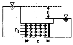
SEEPAGE PRESSURE AND SEEPAGE FORCE
Seepage pressure is exerted by the water on the soil due to friction drag. This drag force/seepage force always acts in the direction of flow.
The seepage pressure is given by 
where,Ps = Seepage Pressure gw = 9.18 km/m3.
here, h = head loss and
(ii) Fs =hAgw
where, Fs = Seepage force.
(iii) fs =igw
where , fs = Seepage force per unit volume.
i =h / z
where, i = Hydraulic gradient.
NOTE: Ps, Fs and fs acts in the same direction i.e, in the direction of flow.
EFFECTIVE STRESSES: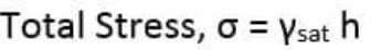
-The pore water pressure (u) is the pressure caused due to the water molecules present in the pores or voids of the soil. It is given by the relation: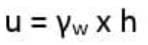
Where,γw=Unit weight of water
Pore water pressure can also be designated as neutral pressure or neutral stress because of the fact that it cannot resist the shear forces in the soil mass.
Note: When the pressure is equal to atmospheric pressure, the pore water pressure is taken as zero.
-The effective stress is given by the formula: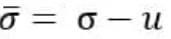
For saturated soil, Effective stress is given by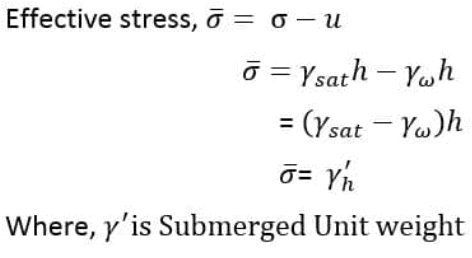
QUICK SAND CONDITION
Quicksand condition is the floatation of particles of cohesionless soil, like fine gravel and sand, due to vertical upward seepage flow. As sand boiling occurs, the bearing capacity and shear strength of the cohesionless soil decrease and the agitations of soil particles become apparent.
How Quicksand Condition Occurs?
Quicksand condition occurs when seepage pressure, which acts in the upward direction, overcomes the downward direction pressure due to submerged weight of soil, and the sand grains are forced apart. The result is that the soil has no capability to support a load.
The soil that experiences quicksand condition would lose shear strength and bearing capacity. The shear strength of cohesionless soil depends on the effective stress. The shear strength is given by: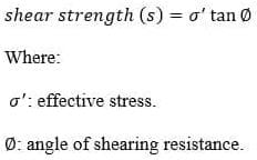
The effective stress is given by the following expression: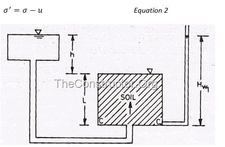
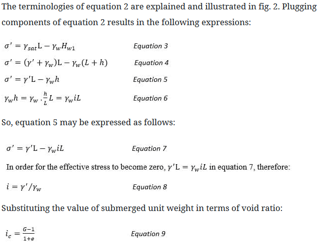
Taking G=2.67, and e=0.67, the result of equation 9 is equal to one.
Thus, the effective stress becomes zero for the soil with above values of G and e, when the hydraulic gradient ‘i’ is unity, i.e. head causing the flow is equal to the length of the specimen.
LAPLACE EQUATION OF TWO DIMENSHIONAL FLOW AND FLOW NET:
(i)
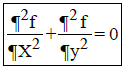
where, f = hydraulic head or head difference between upstream and downstream level or head loss through the soil.
(ii) 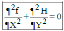
...2D Laplace equation for
Homogeneous soil. where, f = kx H and f = ky . H for lsotropic soil,

SEEPAGE DISCHARGE (q)

where, h = hydraulic head or head difference between upstream and downstream level or head loss through the soil.
shapefactor =  |
where,Nf = Total number of flow channels N1/2 = Total number of flow lines.
Nf = Ny - 1
where, Nd = Total number equipotential drops.
Nf = Total number equipotential lines.
Hydrostatic pressure = U = hwgw
where, U = Pore pressure
hw = Pressure head
Hw = Hydrostatic head - potentialhead
- Seepage Pressure
Ps =h 'gw
where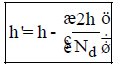
- Exit gradient

where, Size of exit flow field is b × b.
and 
is equipotential drop.
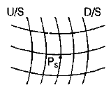
PHREATIC LINE
It is top flow line which follows the path of base parabola. It is a stream line. The pressure on this line is atmospheric (zero) and below this line pressure is hydrostatic.
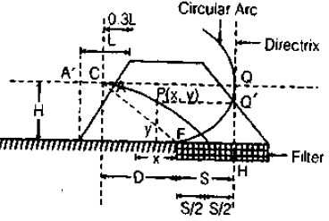
(a) Phreatic Line with Filter
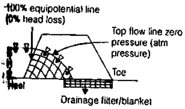
Phreatic line ( Top flow line). ¯
Flows the path of base parabola
CF = Radius of circular arc = 
C = Entry point of base parabola
F = Junction of permeable and impermeable surface
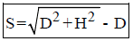
S = Distance between focus and directrix = Focal length
FH = S
(i) q = ks
where, q = Discharge through unit length of dam.
(ii)
(iii)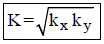 ® For 2D
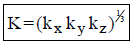 ® For 3D
(b) Phreatic Line without Filter
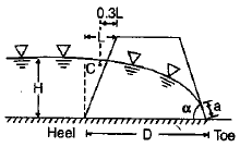
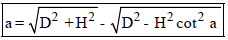
(i) For a< 30º
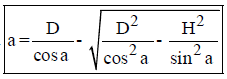
(ii) For a> 30º
| q = k a sin a tan a |
and
For neglecting the flow of sand of down stream. Some Filte is used.
Remember:-
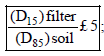
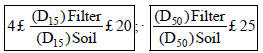
|
2 videos|122 docs|55 tests
|
FAQs on Seepage Analysis - Civil Engineering SSC JE (Technical) - Civil Engineering (CE)
| 1. What is seepage analysis in civil engineering? |  |
| 2. How is seepage analysis conducted in civil engineering? | |
| 3. What are the factors considered in seepage analysis? | |
| 4. Why is seepage analysis important in civil engineering projects? | |
| 5. What are the common methods to mitigate seepage in civil engineering? | |

|
1.8K Views |

|
4.98/5 Rating |

|
Nov 15, 2024 Last updated |
|
2 videos|122 docs|55 tests
|

|
Explore Courses for Civil Engineering (CE) exam
|
|
Semester Notes
,Seepage Analysis | Civil Engineering SSC JE (Technical) - Civil Engineering (CE)
,past year papers
,Summary
,practice quizzes
,Extra Questions
,ppt
,video lectures
,Sample Paper
,Viva Questions
,Important questions
,shortcuts and tricks
,study material
,Seepage Analysis | Civil Engineering SSC JE (Technical) - Civil Engineering (CE)
,Objective type Questions
,MCQs
,Exam
,Free
,Previous Year Questions with Solutions
,Seepage Analysis | Civil Engineering SSC JE (Technical) - Civil Engineering (CE)
,mock tests for examination
;


Seepage Analysis Free PDF Download
Importance of Seepage Analysis
Seepage Analysis Notes
Seepage Analysis Civil Engineering (CE) Questions
Study Seepage Analysis on the App
|
© EduRev
|
Education Revolution
|


Follow Us
|