Stress Distribution in the Soil | Civil Engineering SSC JE (Technical) - Civil Engineering (CE) PDF Download

Chapter 8
Stress Distribution in the Soil
VERTICAL STRESS:
Stress is induced in a soil mass due to weight of overlying soil and due to applied load. This is called vertical stress. Stress in the soil may be caused by:
1. Self weight of soil
2.Applied load of soil
BOUSSINESQ’S THEORY
Assumption:
1. Soil mass is homogeneous, elastic and isotropic
2. Soil mass is semi-infinite (Surface in infinite but depth to finite)
3. Soil is weight less unstressed before application of load. (Self weight of soil is ignored)
4. No change in volume of soil takes place due to applical of the loads.
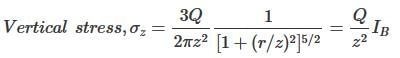
Boussinesq (1985) evolved equations that can be used to determine stresses at any point P at a depth z as a result of a surface point load.
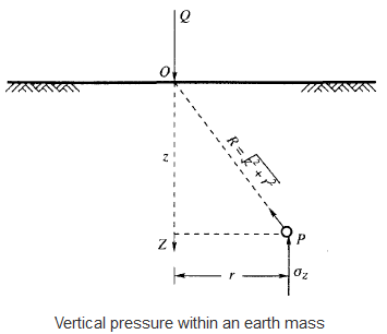
At point P of above figure due to a point load Q,
where,
r = the horizontal distance between an arbitrary point P below the surface and the vertical axis through the point load Q.
z = the vertical depth of the point P from the surface.
IB=Boussinesq stress coefficient =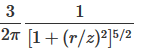
This intensity of vertical stress directly below the point load, on its axis of loading (r=0) is given by:
Boussinesq's Result: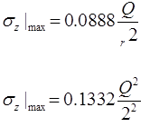
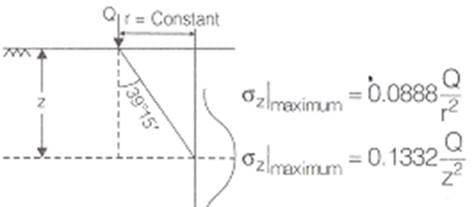
WESTERGAARD’S THEORY:
Assumptions:
(1) The soil is elastic and semi-infinite.
(2) Soil is composed of numerous closely spaced horizontal layers of negligible thickness of an infinite rigid material.
(3) The rigid material permits only the downward deformation of mass in which horizontal deformation is zero.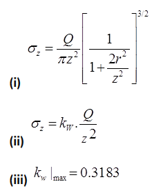
NOTE: Boussinesq’s theory is applicable for Isotropic soil where as westergaards theory is applicable for non- Isotropic soil.
WESTERGAARDS RESULTS
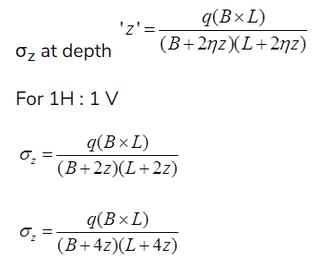
(i) Vertical Stress due to Live Loads
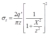
where, σz = Vertical stress of any point having coordinate (x, z)
Load intensity = q'/m
at X = 0
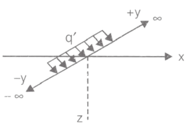
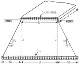
(ii) Vertical Stress due to strip loading
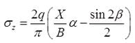
where, σz = Vertical stress at point ‘p’
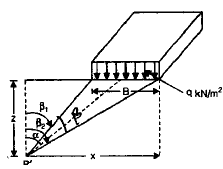
(iii)
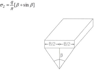
(iv) Vertical stress below uniform load acting on a circular area.
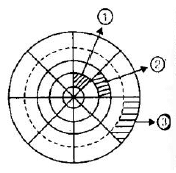
NEWMARKS’S CHART METHOD:
This method is applicable to semi-infinite, homogeneous, isotropic and elastic soil mass. It is not applicable for layered structure. The greatest advantage of this method is that it can be applied for uniformly distributed area of irregular shape. Newmark’s chart is made of concentric circles and radial lines. Normally there are 10 concentric circles and 20 radial lines.
No.of concentric circle =10
No.of radial lines = 20
Influence of area (1)=influence of area(2)=Influence of area(3)
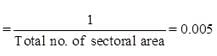
σz = 0.005qNa
where, NA = Total number of sectorial area of Newmark’s chart.
APPROXIMATE METHOD:
(i) Equivalent load method: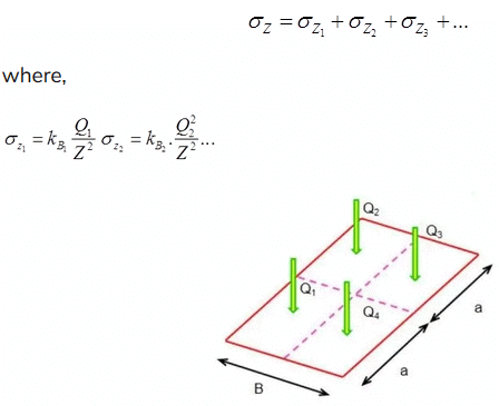
(ii) Trapezoidal Method
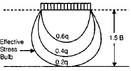
(iii) Stress Isobar method : Area Bounded by 0.2q stress isobar is considered to be stressed by vertical stress on loading.
0.2q =20%Stress Isobar
|
2 videos|133 docs|55 tests
|
FAQs on Stress Distribution in the Soil - Civil Engineering SSC JE (Technical) - Civil Engineering (CE)
| 1. What is stress distribution in soil? |  |
| 2. How is stress distributed in soil? | |
| 3. What are the factors that affect stress distribution in soil? | |
| 4. Why is understanding stress distribution in soil important? | |
| 5. How can stress distribution in soil be analyzed? | |


Semester Notes
,Extra Questions
,Exam
,Sample Paper
,Objective type Questions
,Previous Year Questions with Solutions
,Important questions
,Stress Distribution in the Soil | Civil Engineering SSC JE (Technical) - Civil Engineering (CE)
,Summary
,Stress Distribution in the Soil | Civil Engineering SSC JE (Technical) - Civil Engineering (CE)
,video lectures
,shortcuts and tricks
,practice quizzes
,ppt
,Viva Questions
,mock tests for examination
,Stress Distribution in the Soil | Civil Engineering SSC JE (Technical) - Civil Engineering (CE)
,Free
,MCQs
,study material
,past year papers
;


Stress Distribution in the Soil Free PDF Download
Importance of Stress Distribution in the Soil
Stress Distribution in the Soil Notes
Stress Distribution in the Soil Civil Engineering (CE) Questions
Study Stress Distribution in the Soil on the App
|
© EduRev
|
Education Revolution
|


|


