Shallow Foundation & Bearing Capacity | Civil Engineering SSC JE (Technical) - Civil Engineering (CE) PDF Download
Chapter 13
Shallow Foundation and Bearing Capacity:
FOUNDATION
Foundation is the lowest part of the building or the civil structure that is in direct contact with the soil which transfers loads from the structure to the soil safely. Generally, the foundation can be classified into two, namely shallow foundation and deep foundation.
1. Shallow foundation
 <1
<1
2. Deep Foundation
 >1.5
>1.5
where, Df is Depth of footing B is Width of footing
Types of Footing:
(A) Strip Footing or Continuous footing (L>>B):
-Provided for load bearing wall.
-Provided for a row of columns which are closely spaced that their footings overlap each other.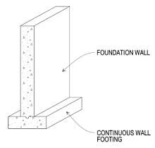
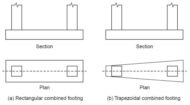
(B) Combined Footing:
-Provided to support more than one column.
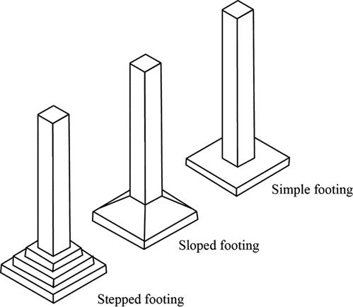
(C) Spread Footing or isolated footing
-Provided to support an individual column.
-Circular,square and rectangular.
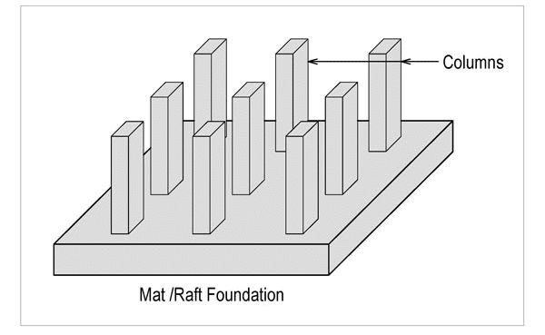
(D) Raft Foundation:
-This is also called mat foundation.
-A mat foundation consists of a single heavily reinforced concrete slab that underlies the entire structure or a major portion of the structure.
-Mat foundations distribute the loads over a large area, thus reducing the intensity of contact pressures.
-Structures founded on relatively weak soils may be supported economically on mat foundations
BEARING CAPACITY:
It is the load carrying capacity of the soil.
Basic definitions:
-Ultimate bearing capacity or Gross bearing capacity (qu): It is the least gross pressure which will cause shear failure of the supporting soil immediately below the footing.
-Net ultimate bearing capacity (qnu): It is the net pressure that can be applied to the footing by external loads that will just initiate failure in the underlying soil. It is equal to ultimate bearing capacity minus the stress due to the weight of the footing and any soil or surcharge directly above it. Assuming the density ofthe footing (concrete) and soil (γ) are close enough to be considered equal, then
qnu = qu - γDf
where,Df is the depth of the footing.
-Safe bearing capacity: It is the bearing capacity after applying the factor of safety (FS). These are of two types:
-Safe net bearing capacity (qns) : It is the net soil pressure which can be safety applied to the soil considering only shear failure. It is given by,
-Safe gross bearing capacity (qs): It is the maximum gross pressure which the soil can carry safely without shear failure. It is given by,
qs = qns + γDf
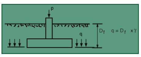 Bearing capacity of footing
METHOD TO DETERMINE BEARING CAPACITY
(i) Rankines Method : Rankine (1885) attempted to determine ultimate bearing capacity of the soil by considering the equilibrium of two elements of the soil, one below the footing and another outside the footing adjacent to the first element.
Following is the equation for ultimate bearing capacity as per Rankine’s theory for cohesionless soil:
where Kp is the Rankine’s coefficient of passive earth pressure.
As per Rankine’s theory, when the depth of foundation is zero, the ultimate bearing capacity is also zero, which is not true. As the Rankine’s theory does not give reliable value of ultimate bearing capacity, it is rarely used in practice. Instead, Rankine’s theory is used to determine the minimum depth of foundation as –
where Ka is the Rankine’s coefficient of active earth pressure and q the maximum pressure applied at the base of the foundation.
(ii) Terzaghi's Method:
Terzaghi’s bearing capacity theory is useful to determine the bearing capacity of soils under a strip footing. This theory is only applicable to shallow foundations. He considered some assumptions which are as follows :
-The base of the strip footing is rough.
-The depth of footing is less than or equal to its breadth i.e., shallow footing.
-He neglected the shear strength of soil above the base of footing and replaced it with uniform surcharge.(γDf)
-The load acting on the footing is uniformly distributed and is acting in vertical direction.
-He assumed that the length of the footing is infinite.
-He considered Mohr-coulomb equation as a governing factor for the shear strength of soil.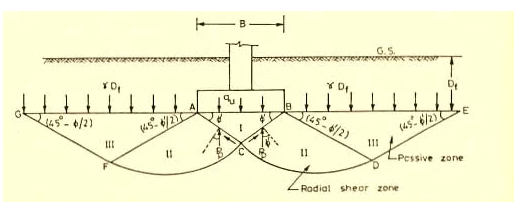
For strip footing

where:
c = cohesion of the soil (kN/m2)
q = total surcharge at the base of the footing
= qappl + γa Df (kN/m2)
qappl = applied surcharge (kN/m2)
γa = unit weight of the overburden material above the base of the footing causing the surcharge pressure (kN/m3)
Df = depth of embedment (m)
γ = unit weight of the soil under the footing (kN/m3)
Bf = footing width, i.e., least lateral dimension of the footing (m)
Nq = bearing capacity factor for the “surcharge” term (dimensionless)
= 
Nc = bearing capacity factor for the “cohesion” term (dimensionless)

Nγ = bearing capacity factor for the “weight” term (dimensionless)

Terzaghi has proposed certain shape factors to take care of the effect of the shape on the bearing capacity. The equation can be written as,
where, sc,sq,sγ are the shape factors whose values for the square and circular footings are as follows
For long footings: sc,sq,sγ=1
For square footings: sc = 1.3, sq=1, sγ=0.8
For circular footings: sc = 1.3, sq=1, sγ=0.6
For rectangular footing of length L and width B:
(iii) Skemptons method (C-soil)
Skempton (1951) has showed that the bearing capacity factors Nc in Terzaghi's equation tends to increase with depth for a cohesive soil.
For (Df/B)≤2.5,(where Df is the depth of footing and B is the base width)
(Nc) for rectangular footing 
For (Df/B)>2.5, Nc for rectangular footing =
(Nc) for circular and square footing = 
The maximum value of Nc is 9.
This analysis is valid for any value of Df/B.
(iv) Meyerhof ’s Method:
- Bearing capacity for a srip footing at any depth.
qu = cNcscdcic + q0Nqsqdqiq + 0.5γBNγsγdγiγ
where s, d and i are shape, depth and inclination factor.
sc,sq,sγ = 1 for strip footing.
Nc,Nq,Nγ depends on the roughness of the footing, depth of the footing and the shape of the footing and the inclination of the loading in addition to the angle of shearing resistance phi.
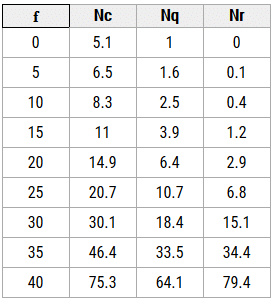
EFFECT OF WATER TABLE:
The position of ground water has a significant effect on the bearing capacity of soil. Presence of water table at a depth less than the width of the foundation from the foundation bottom will reduce the bearing capacity of the soil.
The bearing capacity equation incorporating the ground water table correction factors is given below.

Rw1 and Rw2 are water table correction factors
The water table correction factors can be obtained from the equations given below.
-When the water table is below the base of foundation at a distance ‘b’ the correction Rw2 is given by the following equation
when b=0,Rw2 = 0.5
-When water table further rises above base of foundation, correction factor Rw1 comes in to action, which is given by the following equation.
when a=Df , Rw1=0.5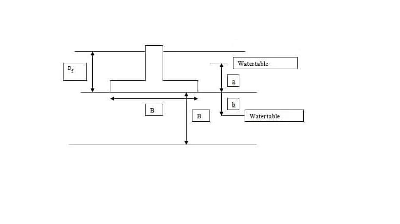
PLATE LOAD TEST:
Plate load test is done at site to determine the ultimate bearing capacity of soil and settlement of foundation under the loads for clayey and sandy soils. So, plate load test is helpful for the selection and design the foundation. To calculate safe bearing capacity suitable factor of safety is applied.
-Bearing Capacity Calculation for Clayey Soils
Ultimate bearing capacity = ultimate load for plate
quf = qup
-Bearing Capacity Calculation for Sandy Soils
quf/qup = Bf/Bp
Finally, safe bearing capacity = ultimate bearing capacity / factor of safety
The factor of safety ranges from 2 to 3.
-Foundation Settlement Calculation on Clayey Soils
Settlement of foundation (sf) = sp x Bf/Bp
-Foundation Settlement Calculation on Sandy Soils
where, quf = Ultimate bearing capacity of foundation
qup = Ultimate bearing capacity of plate
Sf = Settlement of foundations
Sp = Settlement of plate
Bf = Width of foundation
Bp =Width of plate
HOUSEL's APPROACH:
The method suggested by Housel for determining the safe bearing pressure on settlement
consideration is based on the following formula
Q=Apm+Ppn
where Q = load applied on a given plate, Ap = contact area of plate, Pp = perimeter of plate, m = a constant corresponding to the bearing pressure, n = another constant corresponding to perimeter shear.
The equation for a prototype foundation may be written as
Qf=mAf+nPf
where Af = area of the foundation, Pf = perimeter of the foundation.
When Af and Pf are known, the size of the foundation can be determined.
STANDARD PENETRATION TEST:
The standard penetration test is an in-situ test that is coming under the category of penetrometer tests. The standard penetration tests are carried out in borehole. The test will measure the resistance of the soil strata to the penetration undergone. A penetration emphirical correlation is derived between the soil properties and the penetration resistance.
Procedure for Standard Penetration Test:
-The test is conducted in a bore hole by means of a standard split spoon sampler.Once the drilling is done to the desired depth, the drilling tool is removed and the sampler is placed inside the bore hole.
-By means of a drop hammer of 63.5kg mass falling through a height of 750mm at the rate of 30 blows per minute, the sampler is driven into the soil. This is as per IS -2131:1963.
-The number of blows of hammer required to drive a depth of 150mm is counted. Further it is driven by 150 mm and the blows are counted.
-Similarly, the sampler is once again further driven by 150mm and the number of blows recorded. The number of blows recorded for the first 150mm not taken into consideration.. The number of blows recorded for last two 150mm intervals are added to give the standard penetration number (N). In other words,
N = No. of blows required for 150mm penetration beyond seating drive of 150mm. 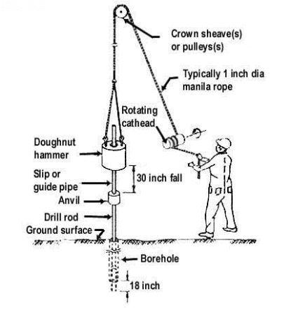
If the number of blows for 150mm drive exceeds 50, it is taken as refusal and the test is discontinued. The standard penetration number is corrected for dilatancy correction and overburden correction.
Corrections in Standard Penetration Test:
Before the SPT values are used in empirical correlations and in design charts, the field ‘N’ value have to be corrected as per IS 2131 – 1981. The corrections are:
-Dilatancy Correction
-Overburden Pressure Correction
1. Dilatancy Correction
The corrected penetration number,
Nc = 15 + 0.5 (Nr -15)
Where Nr is the recorded value and Nc is the corrected value.
If Nr less than or equal to 15, then Nc = Nr
2. Overburden Pressure Correction
The corrected value of ‘N’ is
Nc = CnN
Here Cn is the correction factor for the overburden pressure.
|
2 videos|133 docs|55 tests
|
FAQs on Shallow Foundation & Bearing Capacity - Civil Engineering SSC JE (Technical) - Civil Engineering (CE)
| 1. What is a shallow foundation? |  |
| 2. What is bearing capacity? |  |
| 3. How is the bearing capacity of soil determined? |  |
| 4. What factors affect the bearing capacity of soil? |  |
| 5. How can the bearing capacity of soil be improved? |  |


