Deep Foundation | Civil Engineering SSC JE (Technical) - Civil Engineering (CE) PDF Download

Chapter 14
Deep Foundation
BEARING CAPACITY OF PILES
The ultimate bearing capacity of a pile is the maximum load which it can carry without failure or excessive settlement of the ground. The bearing capacity also depends on the methods of installation.
A. Analytical Method
(i)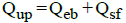
(ii)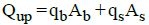
where,
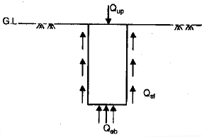
Qup = Ultimate load on pile
Qeb= End bearing capacity
Qsf = Skin friction
qb = End bearing resistance of unit area.
qs = Skin friction resistance of unit area
Ab = Bearing area
As = Surface area
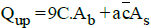
(iii) qb ~ 9C where, C = Unit Cohesion at the base of pile
(iv)  where, a = Adhesion factor
a = Unit adhesion between pile and soil. = Average Cohesion over depth of pile.

where, Fs = Factor of safety
(vi)
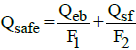
F1 = 3 and F2 = 2
F1 = F2 = 2.5
(vii) For pure clays
B. Dynamic Approach:Dynamic methods are suitable for dense cohesionless soil only.
(i) Engineering News Formula
(a) 
(b) 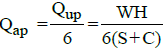
where,
Qup = Ultimate load on pile
Qap = Allowable load on pile
W = Weight of hammer in kg.
H = Height of fall of hammer in cm.
S = Final set (Average penetration of pile per blow of hammer for last five blows in cm)
C = Constant
= 2.5cm for drop hammer
= 0.25 cm for steam hammer (single acting or double acting)
(c) For drop hammer
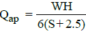
-For single Acting Steam Hammer
Qap= WH/6(S+0.25)
-For Double Acting Steam Hammer
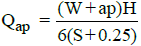
where P = Steam pressure and a = Area of hammer on which pressure acts.
(ii) Hiley Formula (I.S. Formula)
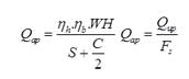

where,
Fs = Factor of safety = 3
ηh = Efficiency of hammer
ηb = Efficiency of blow
ηh = 0.75 to 0.85 for single acting steam hammer
ηh= 0.75 to 0.80 for double acting steam hammer
ηh=1 for drop hammer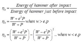
where,
W = Weight of hammer in kg.
P = Weight of pile + pile cap
e = Coefficient of restitutions
= 0.25 for wooden pile and cast Iron hammer
= 0.4 for concrete pile and cast iron hammer
= 0.55 for steel piles and cast iron hammer
S = Final set or penetration per blow
C = Total elastic compression of pile, pile cap and soil
H = Height of fall of hammer.
(C) Field Method
(i) Use of Standard penetration Data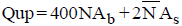
where,N = Corrected S.P.T. Number = Average corrected S.P.T number for entire pile length
Fs = Factor of safety
=4 for driven pile
= 2.5 for for bored pile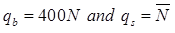
-For non Displacement pile (H-piles)
qb = 200N qs =
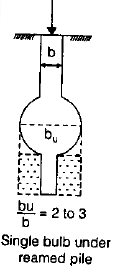
UNDER-REAMED PILE
An ‘under-reamed’ pile is one with an enlarged based or a bulb: the bulb is called ‘under-ream’. Under reamed piles are cast -in-situ piles , which may be installed both in sandy and in clayey soils. The ratio of bulb size to the pile shaft size may be 2 to 3; usually a value of 2.5 is used.
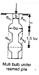
where,bu = dia of bulb, Spacing = 1.5 bu.
Cone Penetration Test: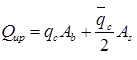
where,
qc = Static cone resistance of the base of pile in kg/cm2. = Average cone resistance over depth of pile in kg/cm2.
Ab= π/4 .(bu)2=Area of bulb (m2).
NEGATIVE SKIN FRICTION:
Negative skin friction is usually a downward shear drag acting on a pile or pile group because of downward movement of surrounding soil relative to the piles. This shear drag movements are anticipated to occur when a pile penetrates into compressible soil layer that can consolidate.
It is reported that, A small relative movement between the soil and the pile of around 10 mm may be adequate for the full negative skin friction to materialize.
(i) Negative skin friction of piles in cohesive soil
where,
Fn=negative skin friction
P= Perimeter of the pile
Lc=pile length in compressible soil
ca=unit adhesion
Unit adhesion=
where,
α= adhesion factor
cu=Undrain Cohesion of the compressible layer
(ii) For cohesion less soils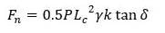
where,
k= lateral earth pressure coefficient
γ= Unit weight of soil
δ= Angle of friction between pile and soil
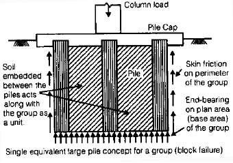
GROUP ACTION OF PILE:
The ultimate load carrying capacity of the pile group is finally chosen as the smaller of the (i) Ultimate load carrying capacity of n pile (n Qup) and (ii) Ultimate load carrying capacity of the single large equivalent (block) pile (Qug).
To determine design load or allowable load, apply a suitable factor of safety.
(i) Group Efficiency (ηg)

Qug = Ultimate load capacity of pile group
Qup = Ultimate load on single pile
For sandy soil - ηg> 1
For clay soil - ηg< 1 and ηg> 1
Minimum number of pile for group action = 3
Qug =qbAb +qsAs
where qb =9C for clays
Ab =B2
qs =
As =4B.L
-For square Group:
Size of group,B = (n -1)S+D
where, n = Total number of pile If size of group is x.x
n =X2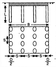
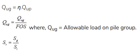
where, Sr = Group Settlement Ratio
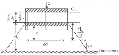
Sg = Settlement of pile group
Si = Settlement of individual pile.
(ii) When Piles are Embended on a Unifrom Clay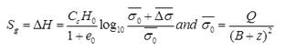
(iii) In case of Sand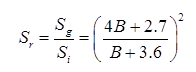
where, B = Size of pile group in meter.
|
2 videos|133 docs|55 tests
|
FAQs on Deep Foundation - Civil Engineering SSC JE (Technical) - Civil Engineering (CE)
| 1. What is a deep foundation? |  |
| 2. What are the common types of deep foundations? | |
| 3. When are deep foundations necessary? | |
| 4. What are the advantages of using deep foundations? | |
| 5. How are deep foundations constructed? | |


Deep Foundation | Civil Engineering SSC JE (Technical) - Civil Engineering (CE)
,Objective type Questions
,Viva Questions
,Exam
,ppt
,practice quizzes
,Sample Paper
,Deep Foundation | Civil Engineering SSC JE (Technical) - Civil Engineering (CE)
,Free
,Important questions
,Deep Foundation | Civil Engineering SSC JE (Technical) - Civil Engineering (CE)
,Semester Notes
,mock tests for examination
,MCQs
,Summary
,study material
,video lectures
,past year papers
,Extra Questions
,shortcuts and tricks
,Previous Year Questions with Solutions
;


Deep Foundation Free PDF Download
Importance of Deep Foundation
Deep Foundation Notes
Deep Foundation Civil Engineering (CE) Questions
Study Deep Foundation on the App
|
© EduRev
|
Education Revolution
|


|


