Resonance


Resonance
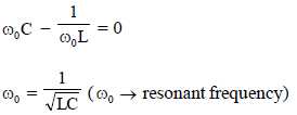
Resonance in an electrical circuit is the condition when the voltage across the circuit becomes in phase with the current supplied to the circuit. At resonance the reactive parts cancel and the circuit behaves as a purely resistive circuit. The power factor at resonance is unity (power factor = 1).
Resonance in lumped RLC circuits is classified into two basic types:
- Series resonance (series RLC circuit)
- Parallel resonance (parallel RLC circuit)
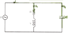
Series Resonance (RLC series circuit)
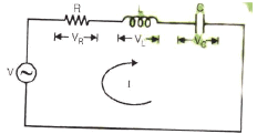
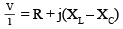
For a series connection of a resistor R, inductor L and capacitor C driven by a sinusoidal source of angular frequency ω, the total impedance Z is
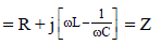
Z = R + j(XL - XC)
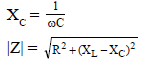
where XL = ωL and XC = 1/(ωC).
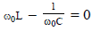
At resonance the imaginary part of Z is zero:
Im{Z} = 0 ⇒ XL - XC = 0
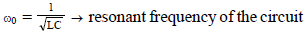
Thus at resonance
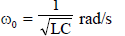
ω0 = 1 / √(LC)
and in hertz
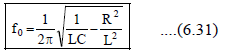
f0 = ω0 / (2π) = 1 / (2π√(LC))
At resonance the impedance equals the resistance:
Z = R

At resonance the circuit current magnitude is maximum and equals
I0 = V / R
Variation of impedance with frequency
The series RLC behaves as follows with respect to frequency:
- For ω < ω0, the circuit is capacitive (behaves like an RC circuit).
- For ω > ω0, the circuit is inductive (behaves like an RL circuit).
- For ω = ω0, the circuit is purely resistive.
- Impedance is minimum at ω = ω0 and equals R.
- Current is maximum at ω = ω0.
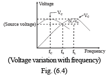
Selectivity and Bandwidth (Series Resonance)
A series resonant circuit is frequency selective. As frequency moves away from resonance on either side, the impedance increases and the current decreases. The frequencies at which the current falls to 1/√2 of its maximum value I0 (i.e. drops by 3 dB) are called the half-power (or 3-dB) frequencies and are denoted by f1 and f2. The difference f2 - f1 is the bandwidth (BW) of the circuit.
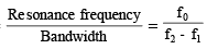
Selectivity is defined as the ratio of the resonant frequency to the bandwidth:
Selectivity = f0 / BW
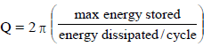
The quality factor (Q) is a measure closely related to selectivity and is defined for series RLC by
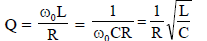
Q = ω0L / R = 1 / (ω0 C R)
- Q of an inductor (having internal series resistance R) is ωL / R.
- Q of a capacitor (with series loss resistance) is 1 / (ωCR).
- Q of a leaky (high-loss) capacitor represented by C in parallel with RP is ωC RP.
For a series RLC circuit at ω = ω0:
For a series circuit the (angular) bandwidth is
BW (angular) = ω2 - ω1 = R / L
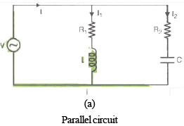
Parallel RLC resonance (Second-order parallel resonant circuit)
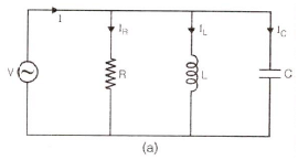
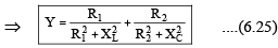
Consider a resistor R in parallel with an inductor L and capacitor C. The admittance Y of the circuit is
Y = G + j(BL - BC)
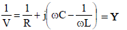
where G = 1/R, BL = -1/(ωL) (susceptance of the inductor), and BC = ωC (susceptance of the capacitor).
At resonance the imaginary part of Y is zero:
Im{Y} = 0 ⇒ BL - BC = 0 ⇒ BL = BC
Hence at resonance
Y = G

and the equivalent impedance is
Z = 1 / G = R
Properties of the parallel resonant circuit
- The resonant frequency is ω0 = 1 / √(LC).
- Below resonance the circuit behaves like an RL circuit (inductive behaviour overall).
- Above resonance the circuit behaves like an RC circuit (capacitive behaviour overall).
- If the conductance G = 0 (i.e. R → ∞), at resonance the circuit behaves as an open circuit (infinite impedance).
- The bandwidth (angular) is approximately 1 / (R C) for the parallel RLC (when defined appropriately for the given topology).
- The quality factor for the parallel circuit Qp can be expressed as Qp = R / (ω0 L) = R ω0 C.
At resonance the admittance is minimum (Ymin = G) and thus the supply current is minimum.

Some important conclusions about parallel resonance:
- The total supply current is minimum at resonance.
- Power factor of the circuit at resonance is unity (cos φ = 1).
- The reactive currents in the inductor and capacitor are equal in magnitude but opposite in phase, so net reactive current from the source is zero.
- Current through the inductor or capacitor can be much larger than the supply current - this is called current magnification.
- Parallel resonant circuits are sometimes called antiresonant circuits because they present a maximum impedance at resonance.


Phasor analysis and example cases
Case 2 - Two branches in parallel with conductances G1 and G2
Consider two branches in parallel each having their own conductance and reactance. The equivalent admittance is
Y = (G1 + G2) + j(BC - BL)
At resonance BC = BL, so
Y = G1 + G2
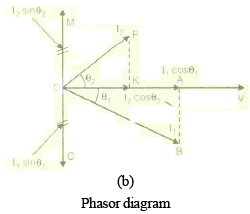
In the phasor diagram corresponding to the circuit, components of branch currents along and perpendicular to the supply current are related by the triangle relations. At resonance the reactive components of currents cancel and supply current equals the vector sum of the resistive components.
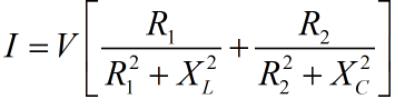
Supply current magnitude is given by
I = V Y
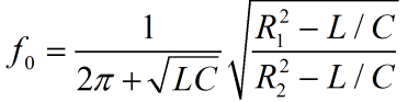
Resonant frequency for this arrangement is unchanged and given by
Case 3 - Tank circuit (important practical case)
A tank circuit is a parallel combination of L and C (often with a parallel resistance representing losses). This is a commonly used resonant circuit in oscillators and filters.
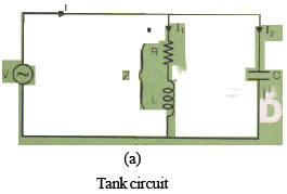
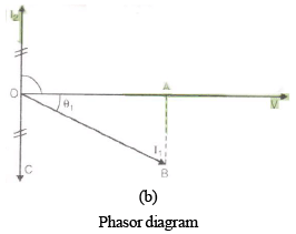
The phasor diagram for the tank circuit shows that the reactive currents in L and C are equal at resonance and oppose each other. The small supply current at resonance is the difference between branch resistive currents (or is due to the losses represented by R).
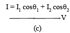
In the phasor diagram:
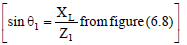
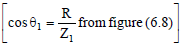
OA = I1 cos θ1
OC = AB = I1 sin θ1
and I1 sin θ1 = I2 (relationship of branch currents)
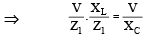


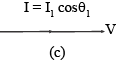
At resonance the supply current I equals the in-phase component of branch current:
I = I1 cos θ1
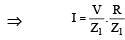

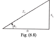
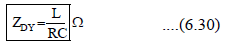
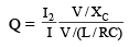
From the derived relations (as shown in the referenced formula images) the dynamic impedance of the tank circuit may be defined as

The dynamic impedance (L / R C) is a useful parameter in analysing transient and small-signal behaviour of the tank.
The resonance frequency of the tank circuit remains
Q-factor for parallel resonance circuits
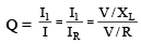
The quality factor Q for a parallel resonant circuit may be defined as the ratio of the current flowing through the inductor (or capacitor) to the total supply current:
- Q = (current in L or C) / (supply current)

From algebraic manipulation of branch and supply currents (see image relations) one obtains expressions for Q such as


Using ω = ω0 at resonance leads to standard alternate forms:


In another common form:
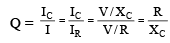
⇒ Q = R ω0 C
⇒ Q = R / (ω0 L)
Q-factor of a tank circuit
- Q-factor is given by
⇒

Anti-resonance (Anti-resonance curve)
- An anti-resonance curve shows the variation of supply current (or admittance) of a parallel resonant circuit with frequency. The circuit presents a maximum impedance (minimum admittance) at the anti-resonant frequency.
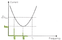
Figure shows the anti-resonance characteristic with pronounced minimum admittance at ω0.
Summary
Resonance occurs when inductive and capacitive reactances are equal in magnitude and opposite in phase so that net reactance is zero. In series resonance impedance is minimum (current maximum) and the circuit behaves like R. In parallel resonance admittance is minimum (current minimum) and the circuit behaves like R (or open if losses are zero). Quality factor Q, bandwidth and selectivity quantify how sharply a circuit responds near resonance. Resonant frequency for ideal lumped L and C is ω0 = 1/√(LC) (f0 = 1/(2π√(LC))). Current magnification is an important feature of parallel resonance; voltage magnification and high circulating currents occur in low-loss tank circuits. These properties are exploited in filters, tuned amplifiers, oscillators and many other electrical systems.
FAQs on Resonance
| 1. What is resonance in electrical engineering? |  |
| 2. How does resonance affect electrical circuits? | |
| 3. What are the applications of resonance in electrical engineering? | |
| 4. How is resonance calculated in electrical circuits? | |
| 5. What are the dangers of resonance in electrical circuits? | |


 | Explore Courses for Electrical Engineering (EE) exam |
 | Get EduRev Notes directly in your Google search |