Two Port Network - 2


Two Port network
Introduction
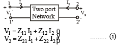
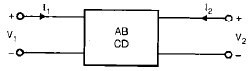
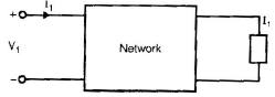
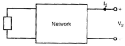
A two-port network is an electrical network with two distinct pairs of terminals (ports) that provide access for connection to external circuits. Each port is a pair of terminals through which a current may enter or leave the network. Two-terminal elements (resistors, inductors, capacitors) form one-port networks; three-terminal devices (for example transistors) can be modelled or configured as two-port networks for analysis. If the network is linear, its behaviour can be fully characterised by a set of two-port parameters that relate voltages and currents at the two ports. These parameters allow prediction of how the network will interact with other networks.
Network parameters - overview
- Z-parameters (open-circuit impedance parameters)
- Y-parameters (short-circuit admittance parameters)
- ABCD parameters (transmission parameters)
- A' B' C' D' parameters (inverse transmission parameters)
- h-parameters (hybrid parameters)
- g-parameters (inverse hybrid parameters)
Z-parameters (open-circuit impedance)
Definition in matrix form:
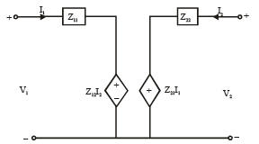
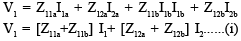
V1 = Z11I1 + Z12I2
V2 = Z21I1 + Z22I2
Meaning of each parameter (measured with the other port open-circuited):
- Z11 - input driving-point impedance with output open (V2=0, I2=0): Z11 = V1/I1 |I2=0
- Z12 - reverse transfer impedance (ratio V1/I2 with I1=0)
- Z21 - forward transfer impedance (ratio V2/I1 with I2=0)
- Z22 - output driving-point impedance with input open (V1=0, I1=0): Z22 = V2/I2 |I1=0
The two controlled sources Z12I2 and Z21I1 are current-controlled voltage sources (CCVS) in the equivalent circuit representation.
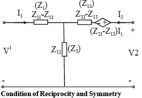
Reciprocity and symmetry (Z-parameters)
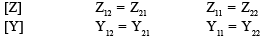
- Reciprocal network: Z12 = Z21.
- Symmetrical network: Z11 = Z22 (and for a symmetrical reciprocal network also Z12 = Z21).
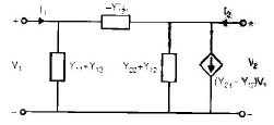
Y-parameters (admittance, short-circuit)
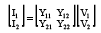
Definition in matrix form:
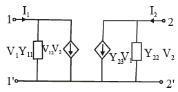
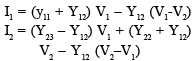
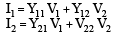
I1 = Y11V1 + Y12V2
I2 = Y21V1 + Y22V2
Meaning of each parameter (measured with the other port short-circuited):
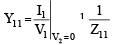
- Y11 - input driving-point admittance with output short (V2=0): Y11 = I1/V1 |V2=0
- Y12 - reverse transfer admittance (I1/V2 with V1=0)
- Y21 - forward transfer admittance (I2/V1 with V2=0)
- Y22 - output driving-point admittance with input short (V1=0): Y22 = I2/V2 |V1=0
Reciprocity and symmetry (Y-parameters)
- Reciprocal network: Y12 = Y21.
- Symmetrical network: Y11 = Y22.
ABCD parameters (Transmission parameters)
Transmission (or chain) parameters relate the sending-end variables to the receiving-end variables. One common form is:
V1 = A V2 + B I2
I1 = C V2 + D I2
Definitions (special cases):
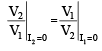
- A = V1/V2 with I2=0 (receiving end open).
- B = V1/I2 with V2=0 (receiving end short).
- C = I1/V2 with I2=0.
- D = I1/I2 with V2=0.


Reciprocity and symmetry (ABCD)
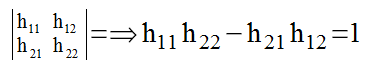
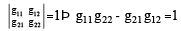
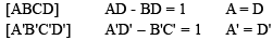
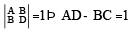
- Reciprocal passive network: AD - BC = 1.
- Symmetrical network: A = D.
Inverse transmission parameters (A' B' C' D')
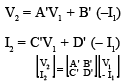
The inverse transmission parameters relate receiving-end variables to sending-end variables:
V2 = A' V1 + B' I1
I2 = C' V1 + D' I1


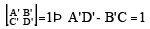
Reciprocity and symmetry (inverse transmission)
- Reciprocal network: corresponding determinant condition holds (same AD - BC = 1 relation transforms accordingly).
- Symmetry: A' = D' for a symmetrical network.
h-parameters (Hybrid parameters)
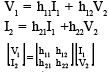
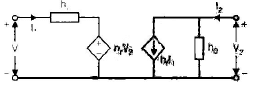
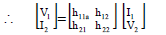
Hybrid parameters are commonly used to model transistors because they mix voltage and current variables so that some parameters are measured with an open input while others with a shorted output. The matrix form used here is:
V1 = h11I1 + h12V2
I2 = h21I1 + h22V2
Interpretation:
- h11 - input impedance with output short-circuited: h11 = V1/I1 |V2=0.
- h12 - reverse voltage gain with input open-circuited: h12 = V1/V2 |I1=0.
- h21 - forward current gain with output short-circuited: h21 = I2/I1 |V2=0.
- h22 - output admittance with input open-circuited: h22 = I2/V2 |I1=0.
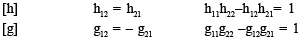
Condition of reciprocity (h-parameters)
h12 = - h21
g-parameters (Inverse hybrid parameters)
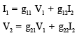
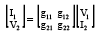
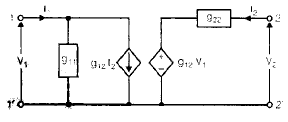
Inverse hybrid (g) parameters use V and I at port 1 and I and V at port 2 in the alternative hybrid arrangement:
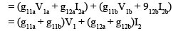
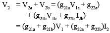
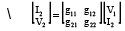
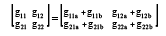
I1 = g11V1 + g12I2
V2 = g21V1 + g22I2

Interpretation:
- g11 - input admittance with output open-circuited.
- g12 - effect of output current on input current (measured with V1=0).
- g21 - forward voltage gain with output open-circuited.
- g22 - output impedance with input short-circuited.
Condition of reciprocity (g-parameters)
g12 = - g21
Interrelations between parameter sets
Relationship between Z and Y
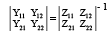
The Y-parameter matrix is the inverse of the Z-parameter matrix. For a 2×2 network, if
Z = [ [Z11, Z12], [Z21, Z22] ]
then
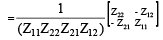
Y = Z-1 = 1/ΔZ [ [Z22, -Z12], [-Z21, Z11] ]
where ΔZ = Z11Z22 - Z12Z21.
ABCD parameters in terms of Z-parameters
Starting from Z relations:
V1 = Z11I1 + Z12I2
V2 = Z21I1 + Z22I2
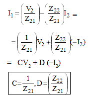
One convenient set of relations (assuming I2 is the current leaving port 2) is:
A = Z11/Z21,
B = (Z11Z22 - Z12Z21)/Z21,
C = 1/Z21,
D = Z22/Z21.
Z-parameters in terms of h-parameters
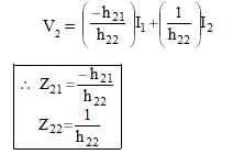
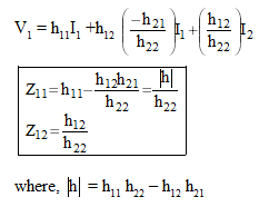
From the h-parameter equations
V1 = h11I1 + h12V2
I2 = h21I1 + h22V2
solve (ii) for V2 and substitute into (i) to get Z parameters. The resulting relations are:
Z11 = h11 - (h12 h21)/h22
Z12 = h12/h22
Z21 = - h21/h22
Z22 = 1/h22
- Find Y parameters in terms of ABCD parameters by inverting the appropriate relations.
- Find h-parameters in terms of ABCD parameters using direct algebraic substitution.
Conditions for reciprocity and symmetry - summary
| Parameter set | Condition for reciprocity | Condition for symmetry |
| Z | Z12 = Z21 | Z11 = Z22 |
| Y | Y12 = Y21 | Y11 = Y22 |
| ABCD | AD - BC = 1 | A = D |
| h | h12 = - h21 | (same condition for symmetry depends on circuit) |
| g | g12 = - g21 | (same condition for symmetry depends on circuit) |
Interconnection of two-port networks
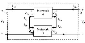
1. Series connection
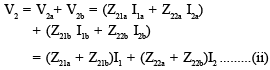
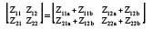
When two two-port networks are connected in series (port-to-port series connection, where corresponding port terminals are series connected), the overall Z-parameters are the sum of the Z-parameters of individual networks:
Ztotal = Za + Zb
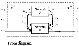
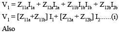
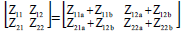
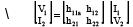
Currents at each corresponding port are same: I1a = I1b = I1, I2a = I2b = I2. Voltages add: V1 = V1a + V1b, V2 = V2a + V2b.
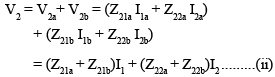
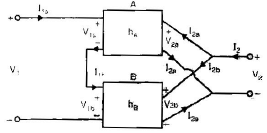
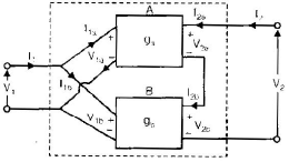
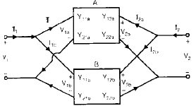
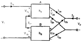
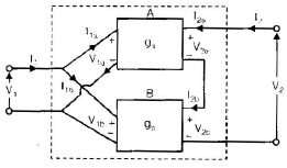
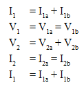
2. Parallel connection
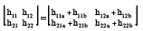
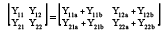
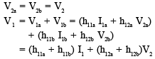
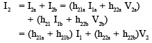
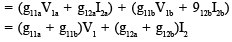
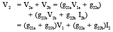
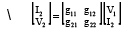
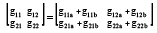
For parallel connection of two networks across both ports, the overall Y-parameters are the sum of the Y-parameters of the individual networks:
Ytotal = Ya + Yb
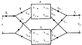
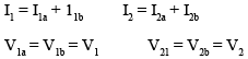
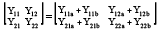
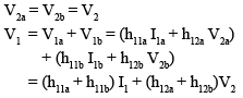
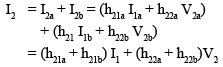
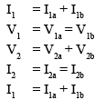
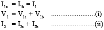
Currents add at each port and voltages are the same across each port: I1 = I1a + I1b, I2 = I2a + I2b, V1a = V1b = V1, V2a = V2b = V2.
3. Series-parallel and parallel-series combinations
Combining networks in mixed series/parallel configurations requires converting to a common parameter set (Z or Y or h) and applying the appropriate add rule. For example, if series connection appears at input side and parallel at output side, write relations accordingly and combine.
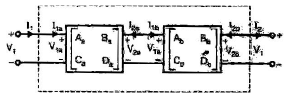
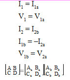
4. Cascade (or cascade-connected) networks
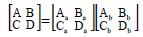
When two two-ports are connected in cascade (output of first connected to input of second, with port polarities observed), the overall ABCD matrix is the matrix product of the individual ABCD matrices in the connection order:
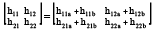
[A B; C D]total = [A B; C D]a × [A B; C D]b
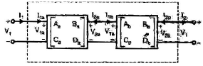
For cascade connection pay attention to current direction: typical convention uses I measured into port 1 and out of port 2; sign conventions must be consistent when multiplying matrices.
Barlett's bisection theorem
- This theorem applies to symmetrical networks. A symmetrical reciprocal network can be split into two identical "halfsections".
- Let ZOC be the open-circuited driving-point impedance of the half-section and ZSCH the short-circuited driving-point impedance of the half-section. Then the two-port Z-parameters of the full symmetrical reciprocal network are given by:
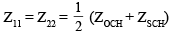
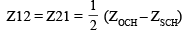
In particular, for many symmetrical networks
Z11 = (ZOC + ZSCH)/2
Z12 = (ZOC - ZSCH)/2
These relations are useful when designing filters and ladder networks where half-sections are used.
Symmetrical lattice network
A symmetrical lattice (bridge) network is a special two-port formed from two series arms and two cross arms, used frequently in equaliser and filter design. For a symmetrical lattice built from a half-section:
Zb ≈ ZOCH
Za ≈ ZSCH
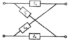
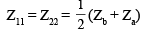
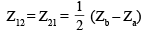
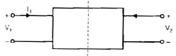
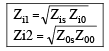
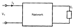
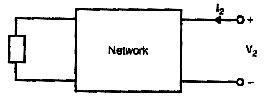
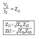
Image impedance
- If Zi1 is the impedance seen at port 1 when an impedance Zi2 is connected at port 2, and Zi2 is the impedance seen at port 2 when Zi1 is connected at port 1, then Zi1 and Zi2 are called the image impedances at port 1 and port 2 respectively.


Useful reminders and practical notes
- Choose the parameter set (Z, Y, ABCD, h, g) that makes interconnection and measurement easiest for a given problem. For example, h-parameters are convenient for transistor small-signal models; ABCD parameters are convenient for cascaded transmission/line sections; Z and Y are natural for series/parallel connections respectively.
- When converting between parameter sets, check determinant conditions (e.g., ΔZ ≠ 0 when inverting Z to obtain Y).
- Always use consistent sign conventions for currents and voltages. Many formulae assume currents are positive into port 1 and out of port 2 unless a different convention is stated.
- Reciprocity conditions depend on the network being passive and reciprocal (no ideal gyrators or active nonreciprocal elements). Symmetry requires identical behaviour when ports are interchanged.
Examples and practice (suggested)
- Convert a given 2×2 Z-matrix to Y-matrix by finding the determinant ΔZ and applying the inverse formula.
- Given h-parameters of a transistor small-signal model, compute the equivalent Z-parameters using the relations linking h to Z.
- For two cascade sections with ABCD matrices given, compute the overall ABCD by matrix multiplication and then find the input impedance for a known load.


Extended reference images and circuit diagrams


Additional diagrams and derivations


Complete interconnection examples and diagrams
Barlett theorem diagrams and lattice examples
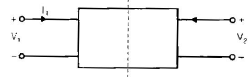
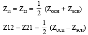
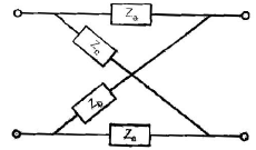
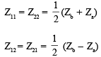
Image impedance and further illustrations

FAQs on Two Port Network - 2
| 1. What is a two-port network in electrical engineering? |  |
| 2. How are two-port networks represented mathematically? | |
| 3. What are the applications of two-port networks in electrical engineering? | |
| 4. How can the parameters of a two-port network be determined experimentally? | |
| 5. What is the significance of the S-parameters in two-port network analysis? | |


 | Explore Courses for Electrical Engineering (EE) exam |
 | Get EduRev Notes directly in your Google search |