Cathode Ray Oscilloscope


The cathode ray oscilloscope (CRO) is an electronic instrument that displays the variation of electrical quantities (usually voltages) as a function of time. It is a versatile laboratory tool used for observing, measuring and analysing waveforms, transient events and phase relationships in electrical and electronic circuits.
Cathode Ray Tube (CRT)
The CRT is the heart of the CRO. It produces a focused beam of electrons, accelerates the beam to a high velocity, deflects it in two orthogonal directions and converts the electron impact into a visible trace on a phosphor-coated screen.
- Main parts of a CRT: electron gun assembly, deflection plate assembly, fluorescent (phosphor) screen, glass envelope and base.
- Working principle: electrons emitted at the cathode are accelerated and formed into a narrow beam. The beam is deflected by electrostatic (or electromagnetic) fields formed by plate pairs to produce a visible spot or trace on the phosphor screen.
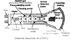
Electron Gun
The electron gun provides a focused, well-controlled electron beam directed down the tube axis.
- Heating element (filament): Heats the cathode to the required temperature for thermionic emission.
- Cathode: A cylindrical element coated with emissive material (commonly barium and strontium oxides) to provide high electron emission at moderate temperature.
- Control grid: A perforated metal cylinder (usually nickel) placed coaxial with the tube. A negative bias on the grid controls the number of electrons that pass through, thus controlling beam intensity (brightness).
- Pre-accelerating and accelerating anodes: These anodes are at high positive potential relative to the cathode and accelerate electrons to high energy. They are typically connected to a common high voltage supply; a typical value used in ordinary CROs is about 1500 V.
- Focusing anode: Produces a field that converges the beam to a small spot on the screen. Focusing may be achieved by electrostatic or electromagnetic means.
Deflection System
Deflection of the electron beam is required to move the spot across the screen and to trace the waveform. In conventional CRT oscilloscopes this is achieved with two orthogonal pairs of plates.
- Vertical deflecting plates (Y-plates): Produce vertical movement of the beam when a voltage is applied across them. The input signal to be displayed is usually applied to the Y-plates.
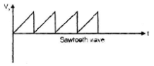
- Horizontal deflecting plates (X-plates): Produce horizontal movement of the beam. In normal time-base operation the X-plates are driven by the internal sweep (time-base) circuit which supplies a sawtooth waveform so the beam sweeps continuously from left to right.
- Electrostatic deflection: Uses plate voltages to steer the beam; deflection is proportional to the deflection-plate voltage for a given geometry and beam energy.
Screen and Envelope
- Phosphor screen: The inside of the front glass is coated with a phosphor that emits light when struck by electrons. Different phosphors give different persistence and brightness.
- Glass envelope and base: Provides vacuum enclosure and mechanical support for pins and connections to external circuits.
Basic CRO Operation and Controls
- Vertical (Y) input and vertical sensitivity: The vertical amplifier conditions the input signal and applies it to the Y-plates. Vertical sensitivity is often expressed as volts per division (V/div) on the screen.
- Horizontal (X) input and time-base: In normal operation the internal sweep generator provides a linear sawtooth waveform to X-plates. Time-base is set by the time/div control, giving horizontal scale in seconds per division.
- Trigger: Ensures the sweep starts at the same point in the input waveform each cycle so that the displayed trace is stationary. Triggering may be internal, external or line, and can be edge or level triggered.
- Coupling: Input coupling options such as DC and AC coupling allow measurement of DC and AC components; AC coupling blocks DC components via a series capacitor.
- Probes: Proper probes (with correct attenuation, compensation and bandwidth) are essential for accurate measurements.
Measurements with a CRO
Voltage measurement
- Peak-to-peak voltage is measured directly from the vertical deflection of the trace by counting the number of vertical divisions and multiplying by V/div.
- The rms value for a sinusoidal waveform is obtained from peak-to-peak as:Vrms = Vpp / (2 × √2)
Current measurement
- Direct current measurement is not done on the CRO. The current in a circuit can be measured indirectly by placing a known small resistor in series and measuring the voltage drop across it; current is then I = V/R.
Frequency and period measurement (time-base method)
- For a periodic waveform, measure the period T by counting the horizontal divisions for one cycle and multiplying by the time/div setting.
- Frequency is the reciprocal of the period:f = 1 / T
Frequency measurement using X-Y mode and Lissajous patterns
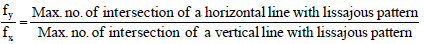
When the CRO is operated in X-Y mode, the horizontal plates are driven directly by an input signal instead of the internal time-base. If two sinusoidal signals are applied simultaneously to X and Y inputs, stationary patterns called Lissajous patterns appear on the screen and can be used to determine frequency ratio and phase difference.
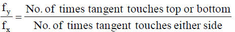
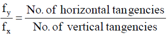
- To measure the frequency of an unknown signal fy using a known reference fx:fy = (m / n) × fxwhere m and n are integers representing the number of tangency points or lobes in the Lissajous figure along the horizontal and vertical directions respectively (use the correct convention depending on how the pattern is counted-commonly fy/fx = m/n).
- For accurate measurement ensure signals are sinusoidal, stable and the display is stationary (the ratio is a simple rational number).
Phase measurement
- Phase difference between two signals can be determined from the Lissajous figure. If the signals have the same frequency and the X input is vx = A cos(ωt) and Y input is vy = B cos(ωt + φ), the pattern is an ellipse whose tilt and intercepts depend on the phase φ.
- When φ = 0 the figure is a straight line with positive slope; when φ = ±90° it is a circle (if amplitudes equal) or a symmetric ellipse; when φ = 180° it is a straight line with negative slope. Exact phase can be obtained from measured intercepts of the ellipse using geometric relations.
Typical Specifications and Practical Considerations
- Bandwidth: The highest frequency at which the CRO can faithfully display waveform amplitude and shape; limited by amplifiers and probe response.
- Sensitivity and resolution: Determined by vertical amplifier gain (V/div), horizontal time/div and physical screen divisions.
- Input impedance: Commonly 1 MΩ in parallel with a small capacitance; probes change effective input impedance and must be compensated.
- Distortion and loading: Probes and input circuitry load the measured circuit and can distort the waveform; use proper probe compensation.
- CRT life and safety: CRTs operate at high internal voltages (e.g., anode voltages of ~1500 V). Handle with caution and follow safety procedures when servicing.
Applications
- Display and measurement of voltage waveforms, transients and pulses.
- Determination of frequency and period of periodic signals.
- Phase measurement between two signals using X-Y mode and Lissajous figures.
- Troubleshooting electronic circuits-observing waveform shapes at test points, checking timing relationships.
- Measurement of signal rise/fall times and transient analysis (subject to bandwidth limits).
Remarks and Modern Context
- Although CRT-based CROs remain educationally important and are still used in laboratories, most modern oscilloscopes are digital storage oscilloscopes (DSOs) which sample the input and display signals on a digital screen, offering features such as storage, advanced triggering and measurement functions.
- The basic principles of beam deflection, time-base sweep and Lissajous patterns remain useful for conceptual understanding and certain specialised measurements.
Summary: The CRO (with its CRT) is a fundamental instrument for visualising electrical waveforms. Understanding the electron gun, deflection system, time-base sweep, triggering, measurement techniques (voltage, current by shunt, frequency by time/div or Lissajous) and practical limitations (bandwidth, probe loading, safety) is essential for accurate use and interpretation of oscilloscope readings.
FAQs on Cathode Ray Oscilloscope
| 1. What is a cathode ray oscilloscope (CRO) and how does it work? |  |
| 2. What are the main components of a cathode ray oscilloscope? | |
| 3. How is a cathode ray oscilloscope used in electrical engineering? | |
| 4. What are the advantages of using a cathode ray oscilloscope? | |
| 5. What are the limitations of a cathode ray oscilloscope? | |


 | Explore Courses for Electrical Engineering (EE) exam |
 | Get EduRev Notes directly in your Google search |