Measurement of Power


Measurement Of Power
Power in AC Circuits - Basic Formula
The average or mean power consumed by a sinusoidal alternating current (AC) circuit over one complete cycle is given by the well-known relation:
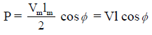
P = Vrms Irms cosφ
where:
- Vrms = root-mean-square value of the voltage,
- Irms = root-mean-square value of the current,
- cosφ = power factor of the load; φ is the phase angle by which current lags (inductive) or leads (capacitive) the voltage.
This expression is valid for single-phase sinusoidal supplies and forms the basis for practical power measurement using instruments called wattmeters.
Wattmeters - Types and Principle
Wattmeters measure the real (active) power in an electrical circuit. The three general categories of wattmeters are:
- Dynamometer (electrodynamometer) type
- Induction type
- Electrostatic type
For practical power measurement in power systems and laboratory work the dynamometer (electrodynamometer) type and induction type are most commonly used. The electrodynamometer type is widely employed for accurate power measurement in both AC and DC circuits and is the classical instrument taught in syllabus-oriented material.
Electrodynamometer (Dynamometer) Type Wattmeter
Construction
The electrodynamometer wattmeter consists essentially of two coils:
- Current coil (also called fixed coil or field coil): connected in series with the load so that it carries the circuit current. It is made of thick conductor to carry large current with small resistance.
- Pressure coil (also called moving coil or potential coil): connected across the voltage to be measured (usually through a suitable series resistor). It is made of fine wire because it carries only a small current proportional to the voltage.
Other important mechanical features are:
- Spring control provides the controlling torque.
- Air friction damping is commonly used to reduce oscillations.
Working Principle and Theory
The moving coil and fixed coil carry currents which produce magnetic fields; interaction between the fields produces a torque that causes deflection of the moving system. The essential relations are:
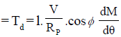
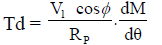
The deflecting torque, Td, is proportional to the product of the instantaneous currents in the two coils and the cosine of the angle between the corresponding fluxes. For sinusoidal steady conditions the mean (average) deflecting torque over a cycle is proportional to the average of the product of instantaneous current in current coil and instantaneous current (or voltage) in pressure coil. This reduces to a quantity proportional to VI cosφ, i.e. the real power.
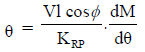
The controlling torque is provided by the spring and is proportional to the angular deflection θ:
Tc = K θ
At steady deflection, equilibrium gives:
Tc = Td
Therefore θ ∝ VI cosφ.
Since the angular deflection is directly proportional to the real power, the scale of an electrodynamometer wattmeter is essentially uniform for sinusoidal waveforms; the instrument therefore indicates power directly.
Coil Impedances and Practical Notes
Denote the resistance and inductance of the pressure coil as rp and Lp respectively, and any additional series resistance used for protection or scaling as R. The total resistance of the pressure coil circuit is then:
Rp = rp + R
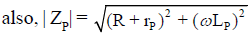
The impedance of the pressure coil circuit is:
Zp = Rp + jωLp
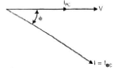
Series resistance is selected so that the pressure coil current is small compared with the line current and so that the potential coil draws a current proportional to the voltage with minimal phase error.
Measurement of Three-Phase Power - Two-Wattmeter Method
Overview
A three-phase, three-wire system would require three wattmeter elements if each phase power is to be measured separately. However, by suitable connection it is possible to measure the total power using only two wattmeters. This is the standard two-wattmeter method. It is applicable to both balanced and unbalanced loads; the algebraic sum of the two wattmeter readings always equals the total instantaneous power delivered to the load.
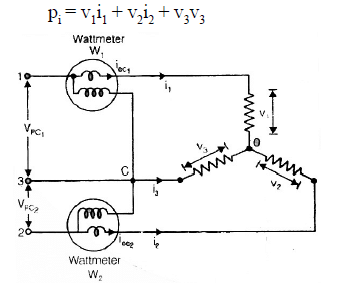
Derivation - Instantaneous Power and Sum of Two Wattmeters
Consider three phase line voltages v1, v2, v3 and phase currents i1, i2, i3. Two wattmeters are connected so that the first wattmeter measures i1 times the potential difference (v1 - v3) and the second measures i2 times the potential difference (v2 - v3). The instantaneous readings are:
P1 = i1(v1 - v3)
P2 = i2(v2 - v3)
The sum of the two instantaneous readings is:
P1 + P2 = i1v1 + i2v2 - (i1 + i2) v3
From Kirchhoff's current law at the load neutral (node O) we have i1 + i2 + i3 = 0, hence (i1 + i2) = -i3. Substituting gives:
P1 + P2 = i1v1 + i2v2 + i3v3
Therefore the sum of the two wattmeter readings equals the total instantaneous power of the three-phase load. The result is general and holds whether the load is balanced or unbalanced.
Balanced Three-Phase Load - Expressions Using RMS Quantities
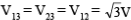
For a balanced star-connected load, phase voltages are equal in magnitude and displaced by 120°. Let:
- Vph = phase (phase-to-neutral) rms voltage
- Iph = phase rms current
- VL = line (line-to-line) rms voltage
- IL = line rms current
- cosφ = power factor of each phase (same for balanced)
For star connection, IL = Iph and VL = √3 Vph. The total three-phase real power is:
P = 3 Vph Iph cosφ = √3 VL IL cosφ
Individual Wattmeter Readings for Balanced Load
For the standard two-wattmeter connection, the readings of the two wattmeters for a balanced load are:
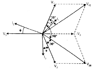
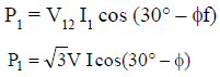
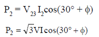
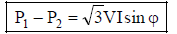
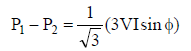
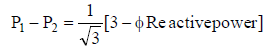
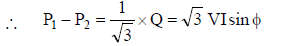
W1 = VL IL cos(φ - 30°)
W2 = VL IL cos(φ + 30°)
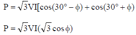
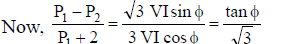
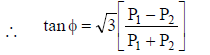
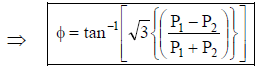
Their algebraic sum is:
W1 + W2 = VL IL [cos(φ - 30°) + cos(φ + 30°)]
Using the trigonometric identity cos(A - B) + cos(A + B) = 2 cos A cos B gives:
W1 + W2 = 2 VL IL cosφ cos30° = √3 VL IL cosφ
which matches the known expression for total three-phase power.
Practical Observations
- The two-wattmeter method measures total three-phase power correctly for both balanced and unbalanced loads; however, interpretation of individual readings is simplest when the load is balanced.
- When the power factor is low and of certain sign, one of the wattmeters may read negative; the algebraic sum still gives total power. A negative reading indicates that the instrument element is delivering power back to the circuit (phase relationship causes reversal of instantaneous torque).
- Two-wattmeter method is convenient because only two instruments are required instead of three, saving cost and simplifying wiring in three-wire systems.
Errors, Sensitivities and Practical Considerations
- Phase displacement errors: If the potential coil current is not exactly proportional to the applied voltage in magnitude and phase (due to inductance of the potential coil or stray reactance), there will be a small error in reading; proper compensation and series resistance selection reduces this error.
- Wattmeter burden: The pressure coil must draw very small power compared with the circuit under test so that it does not appreciably alter the circuit conditions.
- Frequency dependence: Induction type wattmeters and instrument transformers must be used at the rated frequency; significant frequency change affects accuracy.
- Damping and mechanical design: Proper damping, low friction pivots, and robust construction are required for repeatable and accurate readings.
Worked Example
Example (balanced star-connected load): A balanced star load draws a phase current of 10 A at a phase voltage of 230 V. The power factor is 0.8 (lagging). Find the total three-phase real power and the expected two-wattmeter readings if line voltage VL = √3 × 230 V.
Compute total power:
Vph = 230 V
Iph = 10 A
cosφ = 0.8
P = 3 Vph Iph cosφ
P = 3 × 230 × 10 × 0.8
P = 5520 W
Compute line voltage:
VL = √3 × 230 ≈ 398 V
Wattmeter readings (using VL and IL=10 A):
W1 = VL IL cos(φ - 30°)
W1 = 398 × 10 × cos(36°) ≈ 3980 × 0.809 = 3220 W (approx)
W2 = VL IL cos(φ + 30°)
W2 = 398 × 10 × cos(66°) ≈ 3980 × 0.4067 = 1618 W (approx)
Sum: W1 + W2 ≈ 3220 + 1618 = 4838 W. The slight difference from 5520 W is due to rounding in trigonometric approximations in this illustrative calculation; with exact values the sum will equal 5520 W.
Applications and Summary
Measurement of power is fundamental to electrical engineering for billing, energy accounting, machine testing and protection. The electrodynamometer type wattmeter provides direct reading of real power in AC and DC circuits and is the basic instrument used in education and laboratories. The two-wattmeter method is the standard practical technique for measuring total power in a balanced or unbalanced three-phase, three-wire system using only two instruments.


FAQs on Measurement of Power
| 1. What is power measurement in electrical engineering? |  |
| 2. Why is power measurement important in electrical engineering? | |
| 3. What are the different methods of power measurement in electrical engineering? | |
| 4. Can power measurement be done in DC circuits? | |
| 5. How accurate are power measurements in electrical engineering? | |


 | Explore Courses for Electrical Engineering (EE) exam |
 | Get EduRev Notes directly in your Google search |