Insulated Cables


Introduction
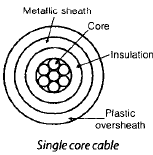
All electric cables consist of three essential parts: the conductor for transmitting electrical power, an insulation to isolate the conductors from each other and from their surroundings, and external protection against mechanical damage, chemical or electro-chemical attack, fire or other external harmful effects.
General Construction Of Cable
High-voltage underground power cables are built around one central core or several cores (commonly two, three or four). Conductors are normally made of stranded copper (often tinned) or aluminium to provide good conductivity and flexibility. Conductors are insulated from one another by materials such as impregnated paper, varnished cambric, vulcanized bitumen or modern polymers. A metallic sheath of lead, lead alloy or aluminium is applied around the insulation to prevent ingress of moisture. Over the metallic sheath a bedding layer (for example paper tape compounded with fibrous material) is provided to protect the sheath and to give a firm base for the armouring which protects against mechanical injury and corrosion.
Requirements Of A Cable
- The conductor should be stranded to provide flexibility and should have adequate cross-sectional area so that the cable can carry the desired load current without excessive heating and with voltage drop within acceptable limits.
- The insulation must be of sufficient thickness and quality to give safety and reliability at the working voltage for which the cable is designed.
- The cable must have mechanical protection so that it can withstand stresses during laying, handling and in-service conditions.
- Materials used in manufacture should provide chemical and physical stability throughout the expected service life; they should resist moisture, oxidation and deterioration with temperature and time.
Conductor Materials Used
The two principal conductor materials are annealed copper and aluminium.
Copper
Copper is typically used where good conductivity and smaller conductor size are required, for example in control circuits, signalling and communication cables and in many low-voltage power applications. Copper conductors used in cables are normally annealed and may be tinned to reduce corrosion.
Aluminium
Aluminium is lighter and less expensive than copper and is commonly used for power cables, especially in larger sizes. Aluminium conductors are available in round, standard or sector-shaped cross-sections suited to power transmission.
Insulation
Insulation separates conductors and prevents current leakage to ground or between cores. Main requirements of insulating materials are:
- High dielectric strength.
- High insulation resistance.
- Good mechanical strength and flexibility.
- Thermal stability over the expected temperature range (commonly from about -30°C to well above 100°C depending on material).
Common Insulation Materials
- Cross-linked polyethylene (XLPE) - widely used for power cable insulation because of good dielectric and thermal properties.
- Polyethylene (thermoplastic) - used for low- and medium-voltage cables; has good dielectric strength but limited temperature rating compared with XLPE.
- Ethylene-propylene rubber (EPR) - a rubber-type insulating compound offering flexibility and good thermal properties.
- Butyl rubber - used in some applications for its dielectric and moisture-resistant properties.
- Polyvinyl chloride (PVC) - used as both insulation and sheath material in many low-voltage cables; inexpensive and flame-retardant.
- Oil-impregnated paper - a classical insulation for high-voltage cables; paper is impregnated with insulating oil to improve dielectric properties.
Parameters Of Cables
Insulation Resistance
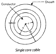
Insulation resistance is the resistance offered by the insulating material between the conductor and the metallic sheath (or between conductors). For a single-core cylindrical cable with conductor radius r and sheath (inner) radius R the insulation resistance depends on the resistivity r (rho) of the insulating material and on the length l of the cable.
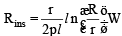
Typical values: the resistivity of impregnated paper at 15°C is of the order of 5 × 10¹² to 8 × 10¹² Ω·m. The resistivity of insulating materials usually falls with temperature approximately according to an exponential relation:
rt = r0 e-a t, where rt is resistivity at t°C, r0 is resistivity at 0°C and a is a material constant.
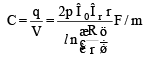
Capacitance
Capacitance of a cable is an important parameter because it determines reactive charging current and voltage distribution along the line. Consider a single-core cable: let the charge per unit length on the conductor be q (C m-1). The electric flux density at radius x in the dielectric and the resulting electric field determine the potential difference between conductor and sheath and hence the capacitance.

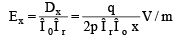
The dielectric properties appear through the relative permittivity εr, and the permittivity of free space ε0 = 8.85 × 10⁻¹² F·m-1. The potential difference between core and sheath is obtained by integrating the electric field; the capacitance per unit length between the core and the sheath for a cylindrical geometry is given by the standard expression (shown in the figure):
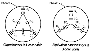
Three-core Cables
Three-core cables are commonly used up to around 11 kV for three-phase distribution. In these cables there is a potential difference between any pair of conductors and between each conductor and the metallic sheath or screen. The capacitance network of a three-core cable therefore includes conductor-to-conductor capacitances and conductor-to-sheath capacitances.
Measurement of Capacitances (Practical Procedure)
Assumptions:
- The dielectric between conductor and sheath is uniform for the purposes of the measurement.
- Let Cc denote the capacitance between any two conductors and Cs denote the capacitance between each conductor and the sheath.
Two practical measurements are used to determine Cc and Cs:
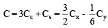
- Measurement 1: Connect any two conductors together and also connect them to the sheath. Measure the capacitance Cx between this combined body and the remaining third conductor.
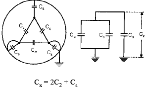
- Measurement 2: Join all three conductors together and measure the capacitance Cy between this combined conductor set and the sheath.
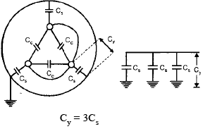
From these two measured values (Cx and Cy) the individual capacitances between conductors and between conductor and sheath can be calculated (the relations and derived expressions are shown in the figures):
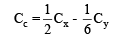

The effective capacitance per phase (i.e., capacitance between each core and neutral or sheath) is useful for system calculations and charging current estimates.
Extra High Voltage (Ehv) Cables
At extra-high voltages the dielectric strength and electric stress distribution in the insulation become critical design considerations. Every dielectric has a finite dielectric strength; if the maximum electric stress exceeds the short-time puncture strength of the dielectric, disruptive breakdown occurs. The maximum electric stress in a single-core cylindrical cable occurs at the surface of the conductor. If one reduces conductor radius to save space, the surface stress increases; increasing the permittivity or changing geometry to reduce size can increase dielectric losses and heating, causing thermal breakdown. Therefore, careful design and grading of the insulation are needed for EHV cables.
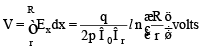
Electrostatic Stress and Field Distribution
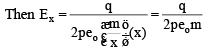
For a cylindrical conductor of radius r inside a metallic sheath of inner radius R, with permittivity ε of the dielectric and with charge per unit length q, the radial electric field at a distance x from the centre is given by the standard cylindrical relation:
E(x) = q / (2π ε x)
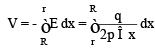
The potential difference between conductor and sheath is obtained by integrating the field:
V = (q / (2π ε)) ln(R / r)

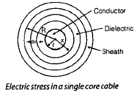
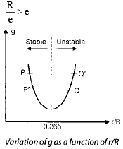
The electric gradient is maximum at the conductor surface (x = r) and minimum at the inner surface of the sheath (x = R). The figures show the variation of radial field and indicate the conductor radius that minimises peak stress for a given geometry and voltage.


Grading Of Cables
Grading is the deliberate distribution of dielectric materials or insertion of metallic interlayers so that the difference between the maximum and minimum electric stress in the insulation is reduced. With effective grading a cable of a given size can be operated at a higher voltage without exceeding the dielectric strength of any portion of the insulation.
Methods of Grading
Capacitance (Permittivity) Grading
Capacitance grading uses two or more layers of dielectric having different relative permittivities, with materials of higher permittivity placed nearer to the conductor. If permittivity could be varied continuously with radius so that the product ε(x)·x is chosen appropriately, the radial electric field could be made nearly uniform through the insulation thickness (the idealised condition and its mathematical form are shown in the figure).

In practice two or three discrete dielectric layers with suitably chosen permittivities are used to approximate the ideal distribution and to equalise maximum field intensities. The layered construction and the corresponding potential and field distributions are illustrated in the figure.
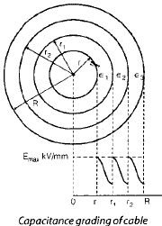
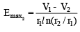
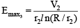
If the maximum electric intensity in each dielectric layer is kept the same, the voltage can be distributed proportionally and the operating voltage of the cable is increased. The relations describing layer thicknesses and permittivities for equal maximum field are provided in the figure.
Intersheath (Metallic-Layer) Grading
Intersheath grading uses a single dielectric but inserts thin metallic intersheaths (screens) within the insulation at intermediate radii. These intersheaths are maintained at intermediate potentials so that the electric field across each dielectric section is reduced. This permits the same insulation thickness to be operated at higher voltage or reduces required thickness for a given voltage.
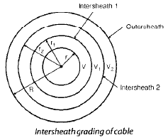
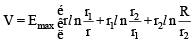
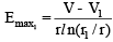
A single-core cable with two intersheaths is shown in the figure; the maximum voltage gradients in the three sections are reduced compared with an ungraded cable and may be made equal by choosing appropriate intersheath potentials and positions.
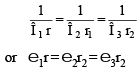
If the maximum and minimum potential gradients in the graded sections are kept the same the distribution of potentials and the required radii of intersheaths can be determined, as illustrated in the accompanying figure.

Applications, Maintenance & Testing Notes
- Cable selection depends on rated voltage, current carrying requirement, installation method (underground, duct, direct burial), mechanical stresses and environmental conditions.
- Regular testing of insulation resistance, partial discharge, capacitance and tan δ (power factor) helps detect deterioration before failure.
- For high-voltage and EHV cables, careful jointing and terminations, correct grading, and provision for thermal dissipation are essential to ensure reliable long-term operation.
- Care during laying (bending radius, avoidance of mechanical damage) and correct bedding/armouring is necessary to maintain cable integrity.
Summary - Insulated cables comprise conductor, insulation and protective sheath/armour. Conductor choice (copper or aluminium), insulation material and construction depend on voltage level and application. Key cable parameters include insulation resistance and capacitance. At high and extra-high voltages special measures such as grading (capacitance/permittivity grading or intersheath grading) are used to control electric stress and avoid dielectric breakdown. Proper testing, installation and maintenance are essential for safe, reliable cable operation.
FAQs on Insulated Cables
| 1. What are insulated cables used for in electrical engineering? |  |
| 2. What are the advantages of using insulated cables? | |
| 3. How is the insulation of cables tested in electrical engineering? | |
| 4. What are the different types of insulation materials used in cables? | |
| 5. How can I select the right insulated cable for my electrical engineering project? | |


 | Explore Courses for Electrical Engineering (EE) exam |
 | Get EduRev Notes directly in your Google search |