Overhead Line Insulators


Overhead Line Insulators
INSULATORS
An insulator is a device designed to separate and prevent the flow of electric current between conductors and to provide electrical insulation of the conductor from the supporting structure or the ground. Overhead line insulators support the conductors mechanically and provide the required electrical insulation in outdoor conditions.
Insulator Materials
Common materials used for overhead insulators are glazed porcelain and toughened (tempered) glass. Each material has advantages and limitations which determine its application.
Porcelain
- The typical composition of electrical grade porcelain is approximately: silica 20%, feldspar 30% and clay 50%.
- Porcelain has good mechanical strength and is resistant to thermal strains; it performs well under weather and temperature changes and gives fewer problems from surface leakage than some other materials.
- The dielectric strength of porcelain is commonly specified as about 15 kV to 17 kV per 0.1 inch of thickness.
- Drawback: Any air impurity trapped inside a sealed porcelain unit can reduce its dielectric strength and may lead to failure.
- Remember: Porcelain is the most commonly used material for insulator manufacture for many overhead applications.
Toughened Glass
- Toughened glass has a high dielectric strength; typical values quoted are about 35 kV per 0.1 inch thickness.
- Transparency of glass makes it easier to detect internal flaws or trapped air bubbles during inspection.
- Glass has a lower coefficient of thermal expansion compared with porcelain, so thermal strain effects are smaller.
- Drawback: Moisture condenses easily on glass surfaces and, because of surface leakage. Glass insulators are widely used in suspension strings for high-voltage lines; however, for distribution voltages they are less common due to surface leakage and moisture issues.
Basic Types of Overhead Insulators
Several types of insulators are used on overhead lines depending on voltage level, mechanical requirements and line configuration. The main types are listed and described below.
Pin Type Insulators
- Pin insulators are mounted on a metal pin fixed to the cross-arm of a pole or tower.
- They are made as single-piece or multi-piece units. Multi-piece construction includes petticoats or rain sheds to increase leakage path length.
- Multiple shells increase the leakage distance and raise the flash-over voltage between the conductor and the earthed pin.
- Pin type insulators are economical and used for lower voltages. They are commonly used up to about 33 kV. Larger pin insulators (multi-piece) may be available for voltages up to 50 kV, but beyond this they become heavy and expensive.
- Remember: Cost of pin-type insulators rises rapidly with increasing operating voltage; cost is roughly proportional to Vx where x > 2.
Suspension Type (Disc or String) Insulators
- Suspension insulators are assemblies of disc units connected in series to form a string. Each disc is a separate insulating unit.
- They are most commonly used for voltages above 33 kV and for high-voltage transmission lines.
- A commonly used disc form is the cemented cap-and-pin or cemented cape type.
- Advantages include flexibility, modular replacement (only the failed disc need be replaced), and the ability to increase insulation by adding extra discs when voltage is raised.
- Remember: A single disc is commonly rated for about 11 kV (typical design practice); therefore the required string length is the number of discs such that the total voltage withstand meets system voltage and safety margins.
Strain Insulators
- Strain insulators are mechanically strong suspension-type assemblies used where the conductor is subjected to large tensile forces, for example at dead-ends, at corners, or at sharp changes of direction.
- The discs of a strain insulator are typically arranged in a vertical plane to resist the mechanical load.
- Remember: Strain insulators take the tension of the conductor at terminations and change-of-direction points.
Shackle (Spool) Insulators
- Shackle insulators are compact, spool-shaped insulators used on low-tension (LT) lines and for house service connections.
- They can be mounted horizontally on a pole or wall and are used for lower-voltage conductors.
Egg (Stay) Insulators
- Egg-shaped insulators are used in guy wires to insulate the lower part of the guy from the pole for public safety.
- They are often fitted at about 3 m above ground level to prevent the guy from being live at hand height.
Post Insulators
- Post insulators are used in substations to support busbars, switchgear and disconnectors.
- They resemble a vertical post and may have a metal base and a conductive cap so that several units can be stacked in series for higher insulation levels.
- In extra-high-voltage substations (for example, 400 kV and above), polycon post insulators (solid-core, puncture-proof polymer types) are often used for outdoor service.
Insulator Strings and Voltage Distribution
An insulator string is a chain of two or more suspension discs (strain insulators) coupled together to provide the required total insulation for the line. The electrical behaviour of a string can be analysed by modelling each disc as a capacitor.
Voltage Distribution along a String
- Each disc may be represented by a capacitance C between adjacent discs; the capacitance from each joint to the earthed tower or structure is often smaller and may be approximated as kC where k typically lies between 0.1 and 0.2 depending on geometry.
- Let Vn be the voltage from the tower (earth) up to the nth unit from the top, and let vn be the voltage drop across the nth unit.
- Using the equivalent capacitive divider, voltages across the units are not equal; units near the line end (bottom) receive higher voltage stress while the units near the tower end are less stressed.
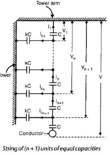
- At junction
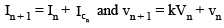
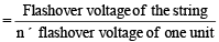
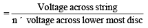
String Efficiency
- String efficiency of an insulator consisting of n units is a measure of how uniformly the applied voltage is shared by the units and is defined by the appropriate ratio of voltages (see formula images below). String efficiency is always less than 100% for a plain string.
- String efficiency generally decreases as the number of units in the string increases if no grading or compensation is used.
Important Observations
- The voltage drop across the unit nearest to the cross-arm (tower end) is minimum and increases towards the line end (bottommost unit).
- The current through the topmost unit (towards the tower) is minimum; therefore its voltage drop is also small.
- The lowest unit in a string is usually fully stressed and is the most heavily utilised.
Improving String Efficiency
The voltage distribution in a plain insulator string is not uniform. Units near the line end are heavily stressed while those near the tower end are under-stressed. Methods are used to improve the uniformity of voltage distribution (increase string efficiency) so that all units make better use of their dielectric capability.
Methods to Improve String Efficiency
- Reduce the shunt capacitance to earth relative to the series capacitance of each unit (reduce the parameter k = C_shunt / C_unit).
- Increase the cross-arm length or otherwise increase distance of the string from tower earth to reduce capacitance to earth.
- Capacitance grading: deliberately increase the capacitance of the discs towards the line end so that voltages become more equal. This requires discs of differing geometry (rare in practice due to manufacturing complexity because manufacturing discs of different capacitances is costly and impractical).
- Static shielding or grading rings: use a metal ring (a grading ring) near the line end to introduce extra capacitance between the line and selected joints, thereby modifying the capacitive divider so that voltage across bottom units is reduced and near-uniform distribution is achieved.
Static shielding (grading ring) uses a large metal ring surrounding the bottom unit and connected to the line. The ring introduces additional capacitances between different joints and the line and increases the effective capacitance of the bottom units.
- Static shielding is often achieved by replacing the ordinary arcing horn at the line end by a grading ring. The ring is shaped and positioned to produce capacitances that counteract the unequal charging currents along the string.
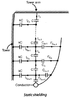
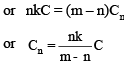
- The design of the grading ring should produce capacitances that balance the charging currents in the string sections; the condition for exact balance is expressed by the capacitance relations shown in the formula image below.
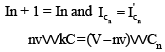
In the schematic expressions, V denotes the operating voltage and Cn denotes the capacitance between the guard (grading) ring and the pin of the nth unit. The relationships between the capacitances and the voltage distribution determine the required ring geometry.
Long Cross-arm Method
String efficiency increases as the ratio K = (capacitance to earth)/(capacitance per insulator) decreases. One way to reduce K is to increase the distance between the string and the tower earth, for example by providing longer cross-arms. However, cross-arm length is limited by cost, mechanical strength, and tower design restraints.
Arcing Horns and Protection
- Every insulator string is normally provided with arcing horns at the tower end and at the line end. If flashover occurs, the arc will form between the horns rather than through the insulator body and the mechanical structure, thereby protecting the insulator units from severe damage.
- Arcing horns can also be combined with grading rings to provide both protective and grading functions.
Practical Notes and Selection Guidelines
- Select insulator type according to operating voltage, mechanical loading and environmental conditions (pollution, coastal salt spray, industrial contamination and icing).
- For voltages up to about 33 kV, pin and glass insulators are commonly used; for higher voltages, suspension strings are preferred.
- Consider ease of maintenance: suspension strings permit replacement of only the damaged disc rather than replacing the entire insulator.
- Take account of dielectric ratings (kV per disc), creepage distance required for polluted environments, mechanical strength (tensile and compressive), and thermal behaviour of the material.
Summary: Overhead line insulators provide both mechanical support and electrical insulation for conductors. Choice of material (porcelain, glass, or modern polymers), insulator type (pin, suspension, strain, shackle, egg, post), string configuration and grading techniques determine the electrical performance and reliability of the line insulation. Proper design of grading rings, arcing horns and geometry of supports improves voltage distribution and reduces the likelihood of flashovers under service conditions.
FAQs on Overhead Line Insulators
| 1. What are overhead line insulators? |  |
| 2. What materials are used to make overhead line insulators? | |
| 3. How do overhead line insulators work? | |
| 4. What are the factors to consider while selecting overhead line insulators? | |
| 5. How are overhead line insulators maintained? | |


 | Explore Courses for Electrical Engineering (EE) exam |
 | Get EduRev Notes directly in your Google search |