Mechanical Design of Overhead Lines

Introduction
- The line should have sufficient current-carrying capacity so that the required transfer can take place without excessive voltage drop or overheating.
- Line losses should be small and the insulation of the line should be adequate to cope with the system voltage.
- The tension in the conductor should be well below the breaking load; a reasonable factor of safety must be used.
- Adequate clearance between the lowest point of the conductor and ground must be maintained at all times.
Line Supports
The supports for an overhead line must be capable of carrying the load due to the conductors and insulators (including ice and wind loads on the conductors) together with the wind load acting on the support itself. The choice and design of supports depend on voltage level, span, terrain, availability of materials and whether the support is expected to behave as rigid or somewhat flexible in the direction of the line.
- Common support types: wooden poles, RCC poles, steel tubular poles and steel towers.
- The design must consider vertical loads (self weight of conductor, insulators and fittings), horizontal wind loads on conductors and tower structure, ice loads where applicable, and dynamic effects during erection and maintenance.
Wooden Poles
- Poles made of chemically treated wood are widely used for distribution lines, especially where good quality timber is readily available.
- For low-voltage (LV) distribution lines typically a single pole supports the span; for higher distribution voltages (e.g., 33 kV) two poles arranged in A or H formation are often used.
RCC Poles
- Reinforced cement concrete (RCC) poles are stronger but generally more costly than wooden poles.
- RCC poles are commonly used for distribution lines up to 33 kV in urban and semi-urban areas where long life and lower maintenance are required.
Steel Towers
- Lines of 66 kV and above are generally supported on steel towers.
- Steel towers are fabricated from painted or galvanised angle sections that can be transported in parts and erected on site.
- Advantages: long life, high reliability and ability to withstand severe weather conditions.
- Height of the tower depends on line voltage and span length.
- For tower design the following forces are considered: vertical loads of conductor, insulators and fittings, wind pressure on conductors and on the tower, ice loads, and unbalanced tensions (e.g., at line terminations, angles and crossings).
Spacing
- There must be adequate spacing between conductors so that they do not come within sparking (flashover) distance of each other even while swinging under wind action.

Where S = Sag in metres; V = Line voltage in kV.
Sag
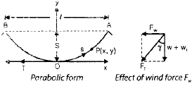
The conductor is assumed flexible and sags below the straight line joining supports due to its weight. The exact shape of a uniform, perfectly flexible conductor under its own weight is a catenary; for most practical overhead line spans with moderate sag the parabola is an acceptable approximation and yields simple formulae.
Supports at Same Level
Consider a span between two supports at the same level. Define the quantities:
- l = Horizontal span (distance between supports), in metres.
- S = Sag at mid-span (vertical distance from supports' level to lowest point of conductor), in metres.
- T = Conductor tension (assumed approximately constant over the span), in newtons (N).
- w = Weight of conductor per unit horizontal length, N/m.
Parabolic approximation (valid for small sag/span ratios):
- The equation relating tension, span, weight and sag is
S = w l² / (8 T)
This can be rearranged to find the required limiting tension for a given sag: T = w l² / (8 S).

Remarks on catenary (exact curve):
- The exact shape is y = a cosh(x/a) - a where a = T / w; the central sag S = a(cosh(l/(2a)) - 1). For spans with large sag the catenary formula should be used; for usual transmission spans the parabolic formula gives convenient and acceptable accuracy.
Effect of Ice and Wind
In addition to its own weight, a conductor may be subject to wind pressure and may carry a coating of ice under severe winter conditions. These increase the effective weight and the horizontal projected area.
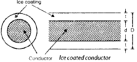
- Let d be the conductor diameter (m) and t the radial thickness of ice (m).
- The overall diameter of an ice-covered conductor is D = d + 2t.
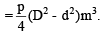
- Volume of ice per metre length of conductor corresponds to the annulus between diameters D and d.
- The specific weight of ice is taken approximately as 8920 N/m³.
- Weight of ice per metre length of conductor (preserving the input empirical expression):
wi = 2.8 × 10⁴ t (d + t) N/m
- The wind pressure is assumed to act horizontally on the projected area of the ice-covered conductor.
- For a wind pressure p (N/m²), the wind load per metre length is
Fw = p D N/m
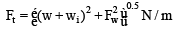
- The combined vertical (effective weight) per metre is W = w + wi and the horizontal wind force per metre is Fw. The total resultant force per metre acting on the conductor under worst conditions is
Ft = √(W² + Fw²) N/m
- The resultant Ft lies in the new plane of the conductor and is inclined to the vertical at an angle γ given by
tan γ = Fw / W

- If T is the limiting tension and Ft is the total force per metre on the conductor under worst conditions, the sag in the new (inclined) plane under parabolic approximation is
S' = Ft l² / (8 T)
The vertical component of sag (vertical clearance) is S' cos γ.

Total Length of Conductor
- The conductor length exceeds the horizontal span because of sag. For parabolic approximation the total length L of conductor over a span l with mid-span sag S can be approximated by
L ≈ l + (8 S²) / (3 l)

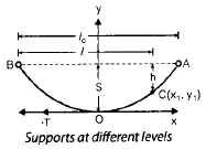
Supports at Different Levels
When two supports are at different elevations, the curve is asymmetric. A complete parabola or catenary can be used with appropriate shift of origin to describe the conductor. The basic parabolic/catenary relations are still applicable after accounting for the difference in support heights.
- Let l be the horizontal span between supports B and C, and lc be the span of the corresponding complete parabola. The design formulae are modified to account for the unequal support heights and the position of the lowest point (sag point) moves towards the lower support.
When supports are at different levels the origin for the parabolic/catenary expression is shifted and the standard relations remain valid after substitution of the shifted co-ordinates.

- The theory remains valid even when both supports lie on the same side of the chosen origin (i.e., when the span is less than the complete parabola half-span), provided the geometry is handled consistently.

Factors Affecting Sag
- Weight of conductor: Sag is directly proportional to the weight per unit length of the conductor.
- Span: A longer span causes more sag; sag is proportional to the square of the span (S ∝ l² for given T and w).
- Conductor tension: Sag is inversely proportional to conductor tension; increasing tension reduces sag but increases stresses on conductors, insulators and supports.
- Ground clearance: To maintain minimum ground clearance it may be necessary to increase tower height if a higher sag is permitted for conductor stress considerations.
- External conditions: Ice accumulation and wind increase effective loads and therefore increase sag unless countered by higher tension or stronger supports.
Sag Template
- A sag template is a practical field tool used to fix tower positions and heights while accounting for required sags and clearances. The template indicates the tower footing line and the expected lowest conductor position for specified span and tension.
- Using sag templates ensures uniformity in erection, correct clearances and compliance with design sag values during line construction.
Practical Considerations and Design Notes
- Choice of conductor: select conductor type and size to provide required current capacity, acceptable line losses, mechanical strength and compatibility with support insulators.
- Factor of safety: choose a suitable factor of safety against conductor breaking load and against insulator and tower failures; consider dynamic loads during erection and fault conditions.
- Insulator selection: insulators must be rated for system voltage, mechanical loads at expected tensions, and environmental conditions (pollution, icing).
- Clearances and regulations: design must meet statutory clearances to ground, roads, railways, buildings and between phases; adhere to relevant national codes and standards.
- Maintenance: design for inspectability and maintenance access; choose materials and coatings (galvanising, painting, preservative treatment) for long life and low maintenance.
Summary
The mechanical design of overhead lines balances electrical requirements (current capacity, insulation) with mechanical constraints (sag, tension, support strength, wind and ice loading). Parabolic approximations provide simple and widely used formulae for sag and conductor length; catenary relations give exact behaviour for large spans. Proper selection of supports (wood, RCC, steel poles/towers), correct spacing, and allowances for environmental loading ensure reliable, economical and safe overhead line performance.
FAQs on Mechanical Design of Overhead Lines
| 1. What are the key factors to consider in the mechanical design of overhead lines? |  |
| 2. How does conductor size affect the mechanical design of overhead lines? | |
| 3. What is the significance of tension and sag in the mechanical design of overhead lines? | |
| 4. How do environmental conditions affect the mechanical design of overhead lines? | |
| 5. What are the clearance requirements for overhead lines in relation to surrounding objects? | |


 | Explore Courses for Electrical Engineering (EE) exam |
 | Get EduRev Notes directly in your Google search |