Protective Relays


Protective Relays
Basic relay terminology
- Relay - An automatic device by which an electrical circuit is indirectly controlled (opened or closed) and which is governed by a change in the same or another electrical circuit.
- Operating force (or torque) - The force or torque that tends to close the relay contacts when the actuating quantity reaches the operating value.
- Restraining force (or torque) - The force or torque opposing the operating force; it prevents operation until the operating torque exceeds it.
- Pick-up (level) - The threshold value of the actuating quantity (current, voltage, etc.) above which the relay operates.
- Reset (or drop-out) level - The maximum value of the actuating quantity below which the relay opens its contacts and returns to the normal position.
- Operating time - Time elapsed from the instant the actuating quantity exceeds the relay pick-up value to the instant the relay closes its contacts.
- Reset time - Time elapsed from the moment the actuating quantity falls below the reset value to the instant when the relay returns to its initial position.
- Setting - The value of the actuating quantity at which the relay is adjusted to operate.
- Back-up relay - A relay that operates after a deliberate delay if the main (primary) relay fails to operate.
- Back-up protection - Protection arranged to clear a fault if primary protection fails; it acts as a second line of defence.
- Primary protection - The protection scheme intended to clear faults in the protected zone; it is the first line of defence.
- Undervoltage relay - A relay that operates when the system voltage falls below a preset value.
- Directional (or reverse-power) relay - A relay that detects the direction of a quantity (for example, power flow or current) and can discriminate between forward and reverse conditions.
- Time-lag relay - A relay that operates after a preset time delay; used for time discrimination in protection schemes.
- Moving-iron relay - An electromagnetic relay using a movable iron element; may be DC-polarised and include a permanent magnet for biasing.
- Thermal relay - Uses electrothermal heating of an element to produce the operating action; commonly used for overload protection of motors.
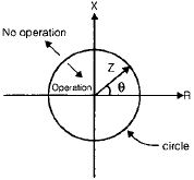
- Conduction (Mho) relay - A relay whose characteristic passes through the origin on the R-X diagram; often called a mho or admittance relay.
- Offset mho relay - A mho relay whose characteristic circle is shifted so as to exclude or include the origin as required.
- Angle (or impedance / ohm) relay - A distance relay whose characteristic on the R-X diagram is a straight line at a specified angle; it measures impedance angle as well as magnitude.
- Earth-fault relay - A relay that operates on earth/ground fault quantities (zero-sequence or residual current) to protect against ground faults.
- Phase-fault relay - Protects against phase-to-phase faults using phase quantities as the actuating signal.
- Negative-sequence relay - Operates on negative-sequence current; used to protect machines against overheating due to unbalanced currents.
- Zero-sequence relay - Operates on zero-sequence or residual current and is used for earth-fault protection.
- Starting relay (fault detector) - Detects abnormal conditions and initiates the action of other elements in the protective scheme.
- Overreach - A condition where a relay operates for a fault located beyond its intended zone of protection.
- Burden - The power (VA) consumed by relay circuitry at rated current.
- Restricted earth-fault protection - Differential protection of a transformer or alternator winding against earth faults confined to the winding; it does not respond to faults outside the restricted zone.
- Residual current - Algebraic sum of phase currents in a multiphase system: for three phases Ires = Ia + Ib + Ic.
What is a protective relay?
- Protective relay - An automatic device that detects abnormal conditions (faults or abnormal operating states) and causes a circuit-breaker to isolate the faulty element to protect equipment and maintain system stability.
Functional characteristics of a protective relay
- Reliability - The relay must operate when it should and not operate erroneously. Typical reliability requirements are very high (for example, 95% or better for the relay action under specified conditions).
- Sensitivity - The relay must be sufficiently sensitive to detect faults of interest; i.e., it must operate when the actuating quantity exceeds pick-up values established by protection requirements.
- Stability - The relay and protection scheme must remain stable (not operate) under normal load conditions and external faults outside the protected zone.
- Speed - The relay must operate fast enough to clear faults without equipment damage, yet not so fast as to respond incorrectly to transient conditions (for example, temporary inrushes or switching transients).
Electromagnetic relays
Attracted-armature relay
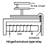
- The relay coil is energised by an operating quantity proportional to system current or voltage; the flux produced gives an electromagnetic attraction force on the armature.
- The electromagnetic force is roughly proportional to the square of the flux in the air gap and therefore to the square of current in many designs.
- This type is used for protection of small equipment and as auxiliary relays (indication, alarm, interposing/slave relays).
- Both AC and DC actuating quantities can be used. In DC relays the attraction is steady; in AC relays the instantaneous force pulsates at twice the supply frequency (double frequency component), which can cause vibration and humming.
- To reduce humming the pole may include a shaded pole (shading coil) construction.
- Typical reset (drop-out) to pick-up ratios range from about 0.5 to 0.9. The ratio for AC versions is generally higher than for DC types.
Advantages
- Low VA burden on current transformers.
- Instantaneous operation (very high operating speed) when designed as such.
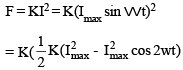
Induction disc relay
- The moving element is an aluminium disc; alternating fluxes produced by coils cut the disc and induce eddy currents.
- One pole face commonly has a shading ring (copper band) so that the flux is displaced in time and space; interaction of displaced fluxes and eddy currents produces torque and rotation.
- Torque produced is roughly proportional to the square of the actuating current when a single actuating quantity is used.
- An adjustable control spring provides resetting torque; a permanent magnet provides eddy-current braking proportional to speed so the disc reaches a steady speed where driving torque equals braking torque.
- Disc relays are typically slow compared with cup relays; used where inverse time characteristics and moderate speeds are acceptable.
- Disc inertia should be small to ensure quick reset when the fault clears.
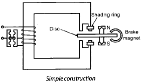
Induction cup relay
- Uses a cup-shaped aluminium rotor; it produces steady, non-vibrating torque and has higher sensitivity and speed than the disc type.
- Typical operating times can be of the order of 0.01 s for high-speed designs.
- Less sensitive to DC transients; therefore historically used for distance and directional functions.
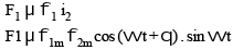
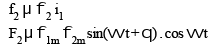
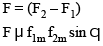
- When two actuating quantities are present, one may produce operating torque while the other provides restraining torque (used in directional units).
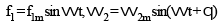
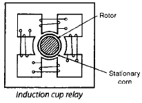
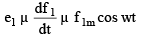
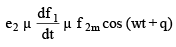
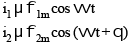
Fluxes f1 and f2 may be expressed as alternating quantities having a phase difference q; eddy currents induced in the rotor are in phase with their induced voltages and the produced force is proportional to f1 f2 sin q. For the same current producing both fluxes, force is proportional to I^2 sin q.
Moving coil relay (permanent-magnet moving coil)
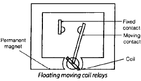
- A moving coil is placed in the field of a permanent magnet; torque is proportional to current in the moving coil and the magnetic field strength.
- Damping is provided by an aluminium former; moving-coil relays are the most sensitive electromagnetic relays and respond mainly to DC quantities or rectified signals.
- Operating torque varies roughly linearly with current, while spring torque is proportional to deflection; many moving-coil relays show an inverse time-current characteristic.
- Typical operating times are of the order of a few cycles depending on design and damping.
Universal torque equation (general form)
- Many electromagnetic relay torque expressions can be written as a combination of terms dependent on current, voltage and their phase relationship. A commonly used general form is:
T = K1 I² + K2 V² + K3 VI cos(φ)
- Here φ is the phase angle between voltage and current; by giving appropriate signs to coefficients K1, K2, K3 and by making some terms zero, operating characteristics of many relay types (overcurrent, voltage restrained, directional, etc.) can be modelled.
Distance relays
A distance relay measures impedance (or a component of impedance) seen by the relay and is used for protection of transmission lines.
- Common classifications: impedance relays, reactance relays, and mho (admittance) relays.
Impedance relay
- An impedance relay operates when the impedance seen by the relay falls below a preset value (the design impedance or reach). It therefore trips for faults within a specified distance on the line.
- Typical torque equation (neglecting spring torque) can be expressed as T = K1 I² - K2 V² so that operation corresponds to Z = V/I being less than a set value.
- The characteristic on a V-I diagram is a circle; on the R-X diagram it is also a circle centered on the origin offset by circuit angle - the relay is nondirectional because the operation is independent of V-I phase relation.
- High-speed variants of impedance relays are commonly used for distance protection.

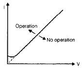

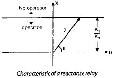
Reactance relay
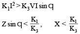
- A reactance relay responds primarily to the reactance component of the measured impedance; the resistance component has negligible effect on its operation.
- It is effectively an overcurrent relay with a directional restraint such that the torque angle of the directional element is tuned to 90°, making the relay respond to the quadrature (reactive) component.
- Reactance relays are useful to protect against faults in the forward direction and are effectively non-directional with respect to the resistive component.
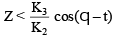
Mho (admittance) relay

- A mho relay is a voltage-restrained directional relay; its characteristic on the R-X diagram is a circle that passes through the origin. It combines both magnitude and direction discrimination.
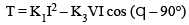
- Operating torque may be represented as T = K3 VI cos(q - t) - K2 V²; the relay operates when the admittance seen by the relay lies within the characteristic circle.
- Because the mho relay is inherently directional and requires only one pair of contacts, it is fast and reduces CT burden compared with multi-element designs.
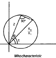
Differential relays
A differential relay operates in response to the vector difference between two or more similar electrical quantities (usually currents). It is widely used for protection of transformers, generators and busbars.
- The usual arrangement compares currents entering and leaving the protected zone; the relay operates when the vector difference exceeds a preset value.
- For current differential protection, the inputs should normally be of the same type and there should be the expected phase relationship (often approximately 180° polarity inversion where CTs are connected appropriately).
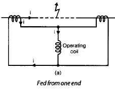
Current balance relay (Merz-Price differential protection)
- Merz-Price protection compares currents from CTs at both ends of an element (transformer winding, feeder, etc.). In a balanced through condition the relay operating coil sees zero differential current; for internal faults a differential current flows and the relay operates.
- Practical systems use pilot wires and ensure equipotential connections so that secondary voltages from CTs circulate without producing an unintentional differential current due to wiring mismatches or unequal burdens.
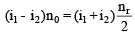
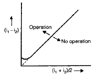
- To reduce maloperation caused by CT saturation and through-fault unbalance, the basic differential relay is modified to percentage differential protection (biased differential). This uses an operating coil and a restraining coil with bias so some restraining torque is proportional to the through current.
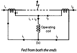
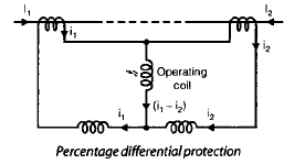
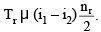
- The operating (differential) current through the operating coil is (i1 - i2). The equivalent restraining current is (i1 + i2)/2 when coils are so arranged. Torques are proportional to ampere-turns of respective coils and the relay operates only when the operating torque exceeds the restraining torque by the set margin.


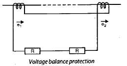
Voltage balance relay
- In voltage balance schemes the secondary voltages of CTs from both ends are connected in opposition so that under normal (balanced) conditions no current flows through the relay coil.
- To ensure linearity under high fault currents, special CT designs (for example, air-cored CTs) may be used so the induced secondary voltage remains a linear function of primary current over a wide range.
Overcurrent relays
An overcurrent relay operates when the actuating current exceeds a preset pick-up value.
Types of overcurrent relays
- Instantaneous relay - Has no intentional time delay; typical response is very fast (on the order of a few cycles). Used where the source impedance to relay is small compared with the line section to be protected.
- Definite time current relay - Operating time is fixed and independent of the magnitude of current (i.e., a time delay set to a fixed value).
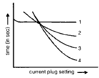
- Inverse time current relay - Operating time is inversely proportional to the magnitude of operating current; the larger the current, the faster the trip.
- Inverse definite minimum time (IDMT) relay - Combines inverse time behaviour at lower multiples of pick-up with a definite minimum time at high multiples. Widely used for distribution line protection.
- Very inverse and extremely inverse relays - Variants of IDMT with steeper inverse characteristics, obtaining faster clearing for very high fault currents while retaining discrimination at lower levels.
Settings used with overcurrent relays
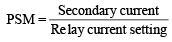
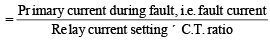
- Current setting / Plug setting multiplier (PSM) - The actual RMS current expressed as a multiple of the setting current (pickup). Example: a 5 A relay set at 200% (10 A pick-up) with 100 A through the relay corresponds to PSM = 10.
- Time setting / Time multiplier setting (TMS) - Scales the operating time of an inverse or IDMT relay. If the relay characteristic gives an operating time of 4 s at TMS = 1 for a given PSM, then for TMS = 0.5 the operating time will be 2 s, and for TMS = 0.2 the time will be 0.8 s.


Buchholz relay (transformer protection)
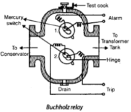
- A Buchholz relay is a gas-actuated relay fitted on transformers with conservator tanks. It detects internal arcing or incipient faults in the transformer by sensing gas generation or violent oil movement.
- For minor faults or slow gas generation, gas accumulates and displaces oil in the relay chamber; a float tilts and an alarm circuit is closed to indicate an incipient fault.
- For severe faults, sudden gas generation or oil displacement causes a rapid oil surge that operates a separate tripping mechanism (trip contacts) to trip the transformer and isolate it from the system.
- Buchholz relays are commonly used on transformers having conservators and are a reliable means of detecting internal insulation failure and arcing before catastrophic failure occurs.
Summary and practical notes
- Selection of relay type depends on the protected equipment, fault type to detect (phase, earth, imbalance, direction), required speed, sensitivity and coordination with downstream/upstream protection.
- Current transformers (CTs) and potential transformers (PTs) are essential for providing scaled signals to relays; CTs must be chosen with appropriate accuracy, knee-point and VA burden characteristics to avoid saturation that can cause maloperation.
- Biasing (percentage differential), directional elements, time grading (TMS) and plug settings (PSM) are standard means to ensure selectivity and stability of protection systems.
- Relay characteristics (time-current curves, impedance/R-X characteristics, mho circles, reactance lines) must be understood and used when coordinating relays across a power system.
FAQs on Protective Relays
| 1. What is a protective relay in electrical engineering? |  |
| 2. How does a protective relay work? | |
| 3. What are the types of protective relays commonly used in electrical engineering? | |
| 4. What are the main functions of protective relays? | |
| 5. How are protective relays tested and maintained? | |


 | Explore Courses for Electrical Engineering (EE) exam |
 | Get EduRev Notes directly in your Google search |