Circuit Breakers

Circuit Breakers
Introduction
The primary function of a circuit breaker is to isolate the faulty portion of an electrical power system when abnormal conditions occur. A protective relay detects the abnormal condition and issues a tripping signal to the circuit breaker, which then opens to interrupt current flow.
- A typical circuit breaker has two main contacts: fixed contact and moving contact.
- Under normal conditions the contacts remain closed and current flows uninterrupted.
- When the breaker must isolate a fault, the moving contact separates from the fixed contact and the current path is broken.
- On separation an arc forms between the contacts. The voltage drop across the arc is called the arc voltage.
- Because the arc column contains ionised gases with a finite conductivity, the arc voltage is nearly in phase with the arc current; its magnitude is relatively small compared with system voltages.
Principles of Arc Interruption
To extinguish the arc and re-establish insulation across the contact gap the breaker must either remove the sustaining energy or allow the gap to regain dielectric strength faster than any restriking voltage can appear. Two broad interruption principles are commonly used:
- High-resistance interruption - increase the arc resistance until the current falls to a value that cannot sustain the arc.
- Current-zero interruption - applicable to AC circuits where the natural zero-crossing of current is used to extinguish the arc; the dielectric strength of the gap must then recover faster than the restriking voltage rises.
High-resistance Interruption
- The arc resistance may be increased by cooling, lengthening, constricting or splitting the arc column.
- If during interruption the voltage across the open contacts becomes larger than the dielectric withstand of the gap, restriking occurs. Thus adequate gap insulation or means to limit the voltage transient is required.
Remember: The high-resistance interruption method is employed for both AC and DC circuit breakers.
Current-zero Interruption (AC)
- This method exploits the natural zero crossing of AC current. The arc is extinguished at or near the current zero provided the dielectric strength of the gap recovers sufficiently rapidly.
- The current should not be interrupted at any instant other than the current zero unless special countermeasures are provided, because interruption away from zero produces large transient voltages across the gap.
- Two main theoretical approaches are used to assess whether the gap will withstand the post-zero restriking voltage: the recovery-rate theory and the energy-balance theory.
Recovery-rate Theory
- The arc is a column of ionised gas. After current reaches zero the electrons and ions must be removed or recombined so the gap regains dielectric strength.
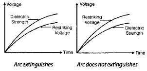
- Extinction occurs if the rate at which the gap recovers dielectric strength is greater than the rate at which the restriking (transient) voltage across the gap rises.
Energy-balance Theory
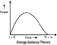
- Immediately after current zero the gap still contains ionised gas and therefore has a finite post-zero resistance. At current zero the instantaneous power is zero because current is zero; when the arc is finally extinguished the gap is fully deionised and its resistance becomes very large.
- If the rate of removal of heat from the arc column is faster than the rate of heat generation the arc will be extinguished.
Remember: If heat removal (cooling) is faster than heat generation the arc is extinguished.
Restriking Voltage and Recovery Voltage
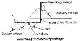
Restriking voltage is the transient voltage that appears across breaker contacts at the instant the arc is extinguished. Recovery voltage is the steady power-frequency root-mean-square voltage that appears across the contacts after the arc has been finally extinguished and transients have died out.
Expression for Restriking Voltage and RRRV
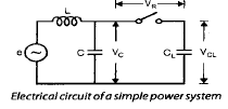
Consider a short-circuit on a feeder beyond the circuit breaker. The line up to the breaker can be represented by its series inductance L and capacitance C per phase. When the breaker opens and the arc is extinguished the current originally flowing through the fault is diverted through the capacitance C and the L-C combination produces a transient oscillation.
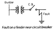
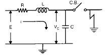
- Let L and C be the inductance and capacitance per phase up to the breaker location.
- When the breaker is closed the short-circuit current flows through R, L and the breaker contacts while C is effectively short-circuited by the fault.
- When the contacts open and the arc is extinguished, current is diverted through C and the L-C network forms a series oscillatory circuit.
- The natural angular frequency of oscillationis

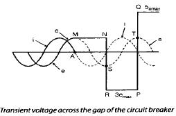
- Voltage across the capacitor (restriking voltage)
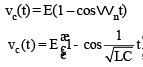
- The maximum value of restriking voltage = 2Epeak = 2 × (peak value of the system voltage).
- Rate of rise of restriking voltage (RRRV)
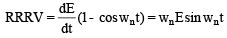
- The maximum RRRV (RRRV)max = ωn Epeak, where ωn is the natural angular frequency.
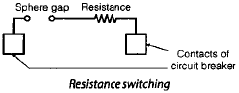
Resistance Switching
To reduce the restriking voltage, the RRRV and the severity of transient oscillations, a resistance may be connected across the breaker contacts; this technique is known as resistance switching. The resistance is placed in parallel with the arc so that a portion of the current flows through the resistor. This reduces the arc current, aids deionisation of the arc path and increases the effective arc resistance.
- Resistance switching is particularly helpful when switching capacitive or low-inductive circuits because it damps oscillations and limits transient overvoltages.
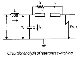
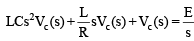
- Voltage equation
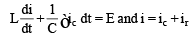
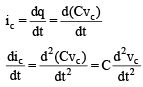
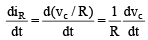
- Capacitor current
- Voltage equation in the s-domain
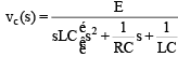
- Capacitor voltage in the s-domain
- Frequency of damped oscillation
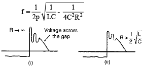
Remember:
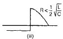
- If the resistance placed across the contacts of the circuit breaker is equal to or less thanthere will be no transient oscillation.

- If R >there will be oscillation.
- R =is known as the critical resistance.
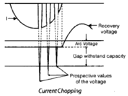
Current Chopping
Current chopping occurs when a circuit breaker interrupts a low inductive current (for example magnetising current of transformers) and the arc quenching forces are sufficient to interrupt current before it reaches its natural zero. Interruption before natural zero converts the energy stored in the magnetic field into a high voltage across the stray capacitance, which can cause restriking.
- The energy stored in an inductance L carrying instantaneous current i is

- This energy may appear as electrostatic energy in stray capacitances:

- Equating these energies gives the voltage that can develop across the stray capacitance when chopping occurs.

Interruption of Capacitive Current
Interrupting capacitive currents (for example an unloaded long transmission line or a capacitor bank) can produce severe voltage transients across the breaker gap.
- When a capacitive circuit is open-circuited the line capacitance CL remains charged. The circuit-breaker stray capacitance C is usually much smaller than CL.
- If interruption occurs at a time when the system voltage is at maximum, the breaker gap voltage may equal the difference between VC (voltage across the breaker capacitance) and VCL (line capacitance voltage); at certain instants the gap voltage can reach twice the maximum value and restriking may occur.
- If the arc restrikes the gap voltage falls toward zero and high-frequency oscillations between the capacitive elements occur until damping reduces them.
- Because of these effects there is a practical problem of high transient voltage when interrupting capacitive currents.
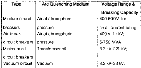
Classification of Circuit Breakers
Circuit breakers are commonly classified by the medium used for arc quenching. Major types include:
- Oil circuit breakers
- Air-blast circuit breakers
- Sulphur hexafluoride (SF6) circuit breakers
- Vacuum circuit breakers
Oil Circuit Breakers
Mineral oil is used as both an insulating and arc-quenching medium. The arc decomposes the oil producing gases (predominantly hydrogen) which absorb arc energy. Oil provides good dielectric strength and cooling, but has disadvantages such as flammability and the possibility of formation of explosive mixtures with air. Heating can also produce carbon particles which reduce oil dielectric strength.
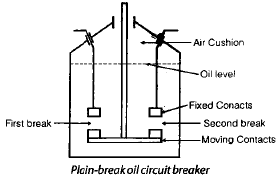
Plain-break Oil Circuit Breakers
- A double-break plain oil circuit breaker separates the contacts in two consecutive gaps. When contacts separate the arc decomposes the oil into gases; the gas surrounds the arc, and oil is displaced from the immediate arc region.
- Arc-quenching actions include elongation of the arc, formation of a gaseous medium with good heat conductivity and dielectric strength, turbulent oil motion and gas formation that help cooling and ion removal.
- A sufficient level of oil above the contacts is required to provide adequate pressure at the arc and ensure deionisation.
- Two breaks in series provide faster elongation without specially fast contact motion, but may have unequal voltage distribution across breaks.
- Plain-break oil breakers are used for low-current breaking at comparatively low voltages (for example low-voltage DC circuits and low-voltage AC distribution). They require large quantities of oil, are slow in operation and are not ideal for auto-reclosing. Typical use up to around 11 kV and interrupting capacities up to a few hundred MVA.
Air-blast Circuit Breakers
- Air is cheap, inert and readily available; air-blast breakers use a high-velocity compressed air jet to quench the arc.
- Advantages: low cost of medium, chemical stability, high-speed operation, elimination of fire hazard, short and consistent arcing time (less contact burning), lower maintenance, suitability for frequent operation and rapid reclosure.
- Disadvantages: need for compressed-air plant (installation and maintenance), high noise levels when air is discharged to atmosphere, problems with current chopping and restriking voltages.
- Switching resistors and equalising capacitors are often connected across interrupters to reduce transients and equalise voltages across multiple breaks. Number of breaks depends on system voltage.
SF6 Circuit Breakers
- Sulphur hexafluoride (SF6) has excellent dielectric strength and arc-quenching properties; at atmospheric pressure its dielectric strength is ≈2.5 times that of air.
- SF6 is inert, non-toxic and non-flammable; a drawback is condensation at low temperatures (liquefaction pressure depends on temperature).
- SF6 breakers are manufactured for voltages from a few kV up to several hundred kV and are preferred for 132 kV and above in many installations.
- The dielectric strength of SF6 increases rapidly after current zero so SF6 breakers can withstand severe RRRV and are capable of breaking capacitive currents without restriking. Current chopping is minimised and required clearances are reduced.
Puffer-type SF6 Circuit Breakers
Puffer-type SF6 breakers are also termed impulse SF6 breakers. They are available across a wide voltage range (typically 3.6 kV up to 765 kV). In these breakers a piston or puffer action compresses SF6 gas and directs the high-pressure gas flow onto the arc to achieve rapid cooling and deionisation.
Vacuum Circuit Breakers
- In vacuum interrupters the dielectric medium is a high vacuum (typically pressures of the order of 10-5 mm Hg or lower). In such vacuum the mean free path of residual gas molecules is very large and electron-gas collisions are negligible; formation of sustained arcs is difficult.
- Breakdown strength in high vacuum depends primarily on gap length, electrode surface condition and electrode material, rather than gas density.
- Vacuum interrupters require much less energy to operate their mechanisms and provide fast contact motion. They are capable of interrupting capacitive and small inductive currents with little transient overvoltage, are suitable for repeated operations, need low maintenance, operate silently and have long service life.
- Vacuum circuit breakers are commonly used up to voltages of about 36 kV; at these voltages a single vacuum interrupter per pole is often sufficient.


Ratings of Circuit Breakers
Under short-circuit conditions a circuit breaker must perform several duties: open the contacts to clear the fault, close onto a fault and carry fault current for a short time while another breaker clears the fault. Therefore, besides rated voltage, current and frequency, breakers are specified by additional ratings:
- Breaking capacity (ability to interrupt fault current)
- Making capacity (ability to close onto a fault)
- Short-time current or short-time withstand capacity (ability to carry fault current for a specified time)
Breaking Capacity
- Breaking capacity is commonly expressed in terms of apparent power (MVA) for three-phase systems:
Breaking capacity (three-phase) = √3 × rated voltage (kV) × rated current (kA)
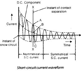
- The breaking capacity may be specified as symmetrical breaking capacity or asymmetrical breaking capacity.
- Symmetrical breaking capacity is the RMS value of the AC component of fault current that the breaker can interrupt under specified recovery voltage conditions.
- Asymmetrical breaking capacity is the RMS value of the total current (including the DC offset) that the breaker can interrupt under specified recovery voltage conditions.
Making Capacity
- The rated making current is the peak value (including the dc component) of the current in the first half-cycle after the breaker is closed onto a short-circuit.
- Making current capability depends on the breaker's mechanical strength and its ability to withstand electrodynamic forces.
- Empirically the making capacity is often related to the symmetrical breaking capacity by a multiplication factor to account for peak and DC components:Making capacity = √2 × 1.8 × symmetrical breaking capacityMaking capacity ≈ 2.55 × symmetrical breaking capacity
Short-time Current and Other Considerations
- Short-time current rating indicates the current the breaker can carry for a specified time without damage (typically a few seconds), allowing coordination between breakers and protection devices.
- Mechanical stresses and thermal stresses caused by fault currents, electrodynamic forces on conductors and contact erosion are important design considerations.
- Auxiliary equipment such as closing and tripping mechanisms, charging compressors (for air blast), SF6 handling systems and monitoring devices also affect overall breaker performance and maintenance.
Practical Notes
- The maximum restriking voltage that can appear across breaker contacts during transient oscillation is twice the peak system voltage.
- RRRV is proportional to the natural frequency of the L-C network; the faster the voltage can rise the more demanding the interrupting dielectric strength must be.
- Resistance switching and damping elements (resistors, surge capacitors and reactors) are commonly used to control transients when switching capacitive or lightly inductive circuits.
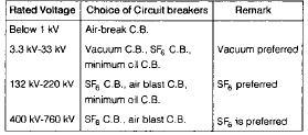
- Choice of breaker type depends on voltage level, interrupting duty, environmental and safety factors, maintenance requirements and cost.
Summary
Circuit breakers isolate faults by opening contacts and extinguishing the resulting arc. Arc extinction uses either increased arc resistance or the natural current zero of AC systems together with rapid dielectric recovery. Transient voltages (restriking voltage and RRRV), current chopping and capacitive switching transients are key phenomena that influence breaker design and auxiliary measures such as resistance switching. Different arc-quenching media - oil, air, SF6 and vacuum - provide trade-offs between dielectric strength, speed, maintenance, safety and control of transients. Breaker ratings - breaking capacity, making capacity and short-time withstand - ensure correct selection and coordination within the power system.
FAQs on Circuit Breakers
| 1. What is a circuit breaker? |  |
| 2. How does a circuit breaker work? | |
| 3. What are the different types of circuit breakers? | |
| 4. What is the purpose of a circuit breaker in a residential electrical system? | |
| 5. How to reset a tripped circuit breaker? | |


 | Explore Courses for Electrical Engineering (EE) exam |
 | Get EduRev Notes directly in your Google search |