Generation of Electrical Energy


Electric Energy Sources
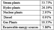
The primary sources of electrical energy in India are fossil fuels (coal, oil, gas), hydropower and nuclear energy. Different types of generating plants contribute to the national mix according to resource availability, capital cost and operating characteristics.
Coal Fuels
Coal occurs in various ranks. Key types used (or considered) in thermal power generation are described below.
- Peat - the first stage in conversion of vegetation into coal; very high moisture (60-90%) and low carbon (5-20%). Not suitable for conventional thermal power plants.
- Lignite - moisture ≈ 30-50%, carbon ≈ 20-40%. Moisture decreases on exposure to air. Can be used in pulverised form for steam generation.
- Bituminous coal - low moisture, carbon ≈ 60-80%, ash ≈ 6-10%. Widely used; semi-bituminous lies between bituminous and anthracite.
- Anthracite - very hard coal with highest carbon content; difficult to pulverise.
Liquid Fuels
Liquid fuels are products of crude oil refining. Typical elemental ranges: carbon 84-87%, hydrogen 11-16% with small amounts of oxygen, nitrogen, sulphur.
Advantages over coal include easier handling/storage, rapid load following and no ash disposal problems.
- Naptha - used in petrochemical and some generating applications; advantages include low cost (relative), low emissions and good turbine efficiency. Typical combined-cycle cycle efficiency ≈ 41%.
- High Speed Diesel (HSD) - also known as gas oil; high calorific value and relatively clean but costly.
- Orimulsion - an emulsion of natural bitumen in water (≈70:30 by weight); calorific value ≈ 7000 kcal/kg and low ash (≈0.2%). Typical composition example: carbon 60.1%, hydrogen 10.1%, oxygen 26.4%, sulphur 2.8%.
- Gas Turbine Fuel Oil - low sulphur and cheaper than HSD; gas turbines burning it require more frequent maintenance.
Gaseous Fuels
- Natural gas - easy to burn, mixes well with air and is transported by pipelines. Clean and environmentally preferable where available.
- Manufactured gases - water gas, producer gas etc., used historically or in specialised plants.
Nuclear Fuels
Common fuels for reactors include natural uranium, slightly enriched uranium dioxide and plutonium-bearing fuels.
- Natural uranium contains ≈ 0.7% U-235. Approximately 1 tonne of natural uranium releases heat equivalent to ~10 000 tonnes of coal.
- Uranium dioxide (UO2) - chemically more stable than metallic uranium; less oxidation concern.
- Uranium carbide - high melting point and good thermal conductivity but not economical for standard power reactors.
- Plutonium-239 - used in fast reactors; highly radiotoxic and handled under strict controls.
Remember: capital cost of nuclear reactors is high, which affects cost of generation compared with conventional coal-fired plants.
Loads And Load Curves
Basic Terms
- Maximum demand - the highest power drawn by a consumer or system at any time.
- Connected load - sum of ratings of all apparatus connected; if everything ran at full rating simultaneously, maximum demand would equal connected load.
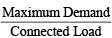
- Demand factor - ratio of maximum demand to connected load, indicating the fraction of connected load contributing to maximum demand.
Diversity Factors
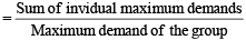
- Group diversity factor - accounts for non-coincident peaks among consumers; the contribution of individual consumer maximum demands to group requirement depends on this factor.
- Remember: group diversity factor is always greater than unity.
- Peak diversity factor - the combined effect of diversity between transformers, feeders and substations; used to estimate effective demand at system peak.

Load Curves
- Chronological load curve - plot of system load against time (commonly over 24 hours). Area under the curve = energy consumed (kWh) in that period.
- Load duration curve (energy load curve) - chronological loads rearranged in descending order. Area under this curve equals area under chronological curve and is useful for plant capacity planning.
- Mass curve - used for hydro studies; gives cumulative energy (or water volume) up to each hour/day and helps determine necessary storage.
Load Factor, Capacity Factor and Utilization Factor
- Load factor - ratio of average load to peak load over a specified period.
- Capacity (plant) factor - ratio of average annual load to rated plant capacity; equivalently, energy produced in a year divided by maximum possible energy if run continuously at rated capacity.
- Utilization factor - ratio of maximum demand to rated capacity of the plant.
Formulas and illustrative diagrams are provided below.


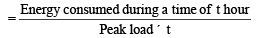
- Load factor can also be expressed as ratio of energy consumed in a period to (maximum load × duration of period).
- Load factor affects plant design, operation and generation cost. A 100% load factor implies constant load (rectangular load duration curve).
- If a plant is always run at rated capacity, capacity factor = 100%.
- Rated capacity of a plant is normally greater than expected maximum load to give reserve margin.
- If rated plant capacity equals maximum load, capacity factor and load factor coincide.
- A low utilization factor implies a standby or reserve plant or a plant installed for future growth; a high utilization factor indicates efficient use of installed capacity.
- Capacity factor = (Load factor) × (Utilization factor).
Base Load and Peak Load Plants
- Base load plants operate continuously and have high load factors; they should have low operating cost (e.g. large coal-fired or nuclear plants, some hydro units).
- Peak load plants operate during periods of high demand and have low load factors; quick starting plants (diesel, gas turbine, pumped storage) are typical.
Depreciation
- Plant value falls from initial cost to salvage value over its useful life due to ageing, wear, corrosion and obsolescence.
- Depreciation charges are annual amounts set aside from income into a reserve to finance future replacement of equipment. Estimating useful life is essential for this calculation.
Diesel Plant
Advantages
- Quick procurement, installation and commissioning; very fast start-up and good operational efficiency (≈ 43-45%).
- No ash handling; low capital cost per kW; relatively small cooling water requirement.
- Can be located near the load centre; suitable for remote or temporary use.
Disadvantages
- Shorter useful life (typical economic life ≈ 5 years); high repair and maintenance costs.
- Limited overload capacity and higher pollution per unit of fuel burnt.
Applications
- Emergency plants - supply essential services when grid supply fails; used for starting auxiliaries in steam stations.
- Mobile plants - trailer-mounted diesel electric units for temporary or emergency power.
- Peak load plants - fast start capability suits peak duty and remote sites where grid supply is unavailable; commonly used during construction stages of larger projects.
Gas Turbine Plant
Gas turbines accept a variety of fuels (liquid or gaseous). Modern plants largely use natural gas (predominantly methane) or liquid petroleum fuels.
- Gas turbines are ideal for peak load duty because of rapid starting and loading capability.
- Operating cost for simple-cycle gas turbine plants tends to be high, making them less suitable for continuous base-load service.
- Smaller gas turbine units (≈ 25 MW) may be used to supply auxiliary power for large thermal stations (starting auxiliaries).
Thermal Power Plant (Coal / Oil Fired)
Thermal plants convert chemical (or nuclear) heat into electrical energy. In a coal-fired plant, coal combustion produces heat to generate steam; expanding steam drives turbines coupled to alternators.
Main Equipment and Auxiliaries
- Coal handling plant - delivers, stores and feeds coal automatically to the furnace; a 200 MW plant may require several thousand tonnes of coal per day.
- Pulverising plant - pulverisation increases coal surface area and improves combustion rate and control.
Advantages of Pulverised Coal
- Rapid and controllable combustion rate to meet load changes.
- Reduced banking losses, lower required excess air, suitability for automatic combustion control and preheated air.
- Enables use of a wide range of coal qualities and quick cold starts.
Disadvantages of Pulverised Coal
- Requires skilled operation, higher plant investment and increased auxiliary power consumption.
Draft Systems
- Draft is the pressure difference causing flow of air and flue gases through the furnace and boiler; flow required is approximately proportional to the square of the required volumetric flow rate.
- Natural draft - created by chimney/stack due to buoyancy of hot gases; used for small boilers only. Chimneys also disperse flue gases to reduce local pollution.
- Mechanical (artificial) draft - using fans (forced draft and/or induced draft) to move air and flue gases; common in large boilers.
Boilers
- Fire-tube boiler - combustion gases pass through tubes surrounded by water; compact and simple but limited to lower pressures and smaller steam capacities.
- Water-tube boiler - water flows in tubes and is heated by external hot gases; suitable for high pressures and large capacities.
Superheater and Reheater
- Superheated steam is steam heated above its saturation temperature at the same pressure, reducing moisture in low-pressure turbine stages and improving efficiency.
- Reheater reheats steam exhausted from intermediate turbine stages to keep it dry through later stages and improve cycle efficiency.
Steam Turbines
- Impulse turbine - steam expands and accelerates in stationary nozzles; high velocity jet impinges on blades and transfers momentum.
- Reaction turbine - partial expansion occurs in nozzle and further expansion occurs over moving blades producing reaction force on rotor.
- Standard coupling speeds for 50 Hz systems are typically 3000 rpm (two-pole) and 1500 rpm (four-pole) machines; governors maintain speed under load changes.
Condenser
- Condenses exhaust steam from the turbine to maintain low back pressure (often below atmospheric), increasing expansion and plant efficiency.
- High vacuum maintenance in the condenser is critical; modern plants commonly use surface condensers.
Cooling Towers
Large condensers require significant cooling water. Typical order-of-magnitude: roughly 100 kg of cooling water per 1 kg of steam; very large plants require millions of gallons per day.
Economiser and Air-preheater
- Economiser recovers heat from flue gases to preheat feed water, improving boiler efficiency at the expense of extra capital and maintenance.
- Air-preheater extracts remaining heat from flue gases to heat incoming combustion air; cooling flue gases by ≈20°C may raise plant efficiency by ≈1%.
Hydro Electric Plants
Water Power Principle
- Falling water converts potential energy into mechanical energy in turbines which drive alternators to generate electricity.
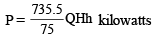
In the power expression, the usual variables are:
- Q - discharge (m³/s)
- H - effective head (m)
- η - overall turbine-alternator efficiency (decimal)
Advantages of Hydropower
- Long useful life (≈ 50 years) and low operating costs since no fuel is consumed in operation.
- No standby fuel losses; rapid start and synchronisation; rapid load adjustment.
- Robust plant behaviour, low maintenance cost and sustained efficiency with age compared with thermal plants.
Disadvantages
- High capital cost per kW (dam, civil works); generation dependent on water availability - dry years can significantly reduce output.
- Firm capacity (guaranteed output) may be low and often requires backup from thermal plants.
Hydrology and Water Availability
- Run-off - portion of rainfall available as stream flow after losses by evaporation, infiltration and vegetation uptake.
- Run-off depends on rainfall patterns, geology, catchment shape/size, topography, soil type, vegetation and weather.
- Stream flow - measured in m³/s by gauging; long-term flow records are essential to estimate available hydropower.
- Hydrograph - stream flow vs time for a site (analogous to chronological load curve).
- Flow duration curve - rearrangement of hydrograph flows in descending order.
- Mass curve - cumulative runoff volume vs time; slope = rate of flow.
- Storage - enables transfer of water from periods of surplus to deficit, increasing firm capacity and total energy produced.
- Pondage - small local storage near power house to manage hour-to-hour load fluctuations (capacity typically sized for 24-hour variations).
Site Selection Factors
- Reliable long-term river run-off records (average, minimum and maximum flows and their periods).
- Storage potential and reservoir location relative to power house.
- Available head - higher head reduces required stored water and penstock/turbine sizes.
- Water quality - polluted water can accelerate corrosion and damage metallic parts.
- Sedimentation - silt reduces reservoir capacity and can damage turbines.
- Access - transport of construction material and heavy machinery must be feasible (roads, rail links).
Classification of Hydro Plants
- Run-of-river without pondage - use inflow as it arrives; no control on flow. Can supply substantial base load during high flow but limited during lean periods.
- Run-of-river with pondage - small local storage for hourly regulation; can operate as base or peak plant depending on flow.
- Reservoir plants - large storage behind a dam for seasonal regulation; increase firm capacity and permit flexible operation as base or peak plant depending on storage and inflow. Example: Bhakra (India) is a reservoir type plant.
Classification According to Head
- Low head - head < 30="" m;="" turbines:="" kaplan="" or="" propeller;="" power="" house="" near="" dam,="" surge="" tank="" often="" not="" />
- Medium head - 30-100 m; turbines: Francis or Kaplan; open channel to forebay and penstocks to turbines.
- High head - > 100 m; turbines: Francis for heads below ~200 m, Pelton for very high heads.
Key Civil and Hydraulic Components
- Dam - creates artificial head and storage; typically the most expensive element of the project.
- Forebay - enlarged water body at intake to store water temporarily for hourly fluctuations.
- Intake - provides controlled entry of water to conduits or penstocks.
- Surge tank - absorbs sudden changes in flow to prevent water hammer and vacuum; stabilises pressure and velocity in penstock; located close to powerhouse or sometimes underground.
- Penstock - conveys water from forebay/reservoir to turbine; low-pressure penstocks may be open channels or flumes; high-pressure penstocks are thick steel pipes, each turbine generally has its own penstock.
- Spillway - discharges excess water during floods (spillway, by-pass tunnel or conduit).
- Tailrace - discharges water from turbine back to river; design ensures free exit and avoids interference with turbine performance. Impulse turbines discharge directly and do not require a draft tube.
Hydraulic Turbines
Hydraulic turbines convert water energy into mechanical energy to drive alternators. They are efficient (often > 90% at full load), robust and can pick up load rapidly. Turbines are classified as impulse or reaction.
Specific Speed
The specific speed (metric units) Ns is defined as the speed of a geometrically similar turbine which would develop 1 metric hp under a head of 1 metre. The practical formula relating specific speed is:

Where Ns = specific speed (metric units), N = turbine speed (rpm), Pt = output (metric hp), H = effective head (m).
Types of Turbines by Head and Specific Speed
| Types of Turbine | Head | Specific speed (metric units) |
|---|---|---|
| Pelton | Above 200 m | 10-50 |
| Francis | 30-200 m | 60-300 |
| Propeller / Kaplan | Less than 30 m | 300-1000 |
Pelton Turbine
- Impulse turbine suitable for high head and low flow volumes (not suitable for heads below ≈ 200 m).
- Specific speed typically 10-50.
Francis Turbine
- Reaction turbine suitable for medium heads and flows; power developed due to both water velocity and pressure differences across runner blades.
Propeller and Kaplan Turbines
- Propeller (axial-flow) turbines suit low head and large flow rates (heads < 30="" />
- Kaplan turbine is a propeller type with adjustable blades, maintaining high efficiency over a wide range of discharges and part-loads; typical speeds higher than Francis (≈ 400-1500 rpm).
Bulb Turbines
- Axial-flow, compact units where water flows coaxial with the shaft; well-suited to very low heads and tidal schemes.
- Advantages: reduced civil cost, compactness, high efficiency under widely varying heads; commonly used in small hydro schemes.
- Disadvantages: access to the generator may be difficult for maintenance; relatively low rotational inertia.
Pumped Storage Plants
- Pumped storage plants store energy by pumping water to a higher reservoir during off-peak (low cost) periods and releasing it to generate during peak demand.
- During peak, water flows from head pond through penstocks to generate power; during off-peak the same units (pumps/turbines) pump water back from tail pond to head pond.
- Remember: pumped storage supplies peak loads at lower cost than running steam or nuclear plants at variable duty. They provide very fast starting (≈ 2-3 s) and can reach full load in ≈ 15 s, and support load-frequency control while improving load factor of base plants.
Nuclear Power Plants
Nuclear energy can supply large-scale, long-term energy needs. Nuclear plants have high capital cost but relatively low fuel requirements.
Main Advantages
- Very small quantities of fuel produce large energy amounts; fuel costs are a small part of generation cost.
- Less area required compared with some conventional steam plants; reduced reliance on coal/oil.
- Fossil fuel conservation when nuclear plants augment supply.
Energy-Mass Relationship
- Einstein's mass-energy relation: E = mc², where E is energy (J), m is mass (kg) and c is speed of light (≈ 3 × 10⁸ m/s).
- Atomic mass unit (amu) is defined as one-twelfth the mass of a carbon atom; mass of proton and neutron ≈ 1 amu each. 1 amu ≈ 1.6604 × 10⁻²⁴ g. One amu corresponds to ≈ 931.1 MeV.
Isotopes and Radioactivity
- Isotopes - same atomic number but different mass numbers (e.g. uranium occurs as 92U-235 and 92U-238).
- Natural uranium contains ≈ 99.23% U-238 and ≈ 0.72-0.7% U-235.
- Radioactivity - spontaneous disintegration of unstable nuclei; artificial radioactivity can be produced by neutron bombardment. Emitted radiations include α (alpha) particles, β (beta) particles, γ (gamma) rays and neutrons.
- α-particles are helium nuclei, written 2He4 (or He-4 nucleus).
Sample α-decay reactions provided:
- 92U238 → 2He4 + 90Th234
- 94Pu239 → 2He4 + 92Th235
Canning (Cladding)
- Fuel elements are canned (clad) in materials such as aluminium, magnesium, beryllium or stainless steel so that fuel does not contaminate the coolant and to reduce radiation hazards.
Coolant
- Coolant removes heat from the fuel elements and transfers it to the steam cycle or heat exchanger.
- Desirable coolant properties: low neutron absorption, non-oxidising, non-toxic, chemically and radiatively stable, good heat transfer capability.
- Examples of coolants: carbon dioxide (gas-cooled designs), liquid metals, ordinary water and heavy water.
Moderator
- Moderator slows down fast neutrons produced in fission to thermal energies where fission cross sections of fissile isotopes are higher.
- Good moderator properties: low neutron capture cross section, chemical inertness, stability under irradiation, availability and effectiveness in energy reduction per collision.
Fissile and Fertile Materials
- Fissile materials - undergo fission with thermal neutrons: U-235, U-233, Pu-239. U-235 is naturally occurring (≈ 0.72% of natural uranium).
- Fertile materials - not fissile but can be converted to fissile isotopes by neutron absorption (e.g. U-238 → Pu-239, Th-232 → U-233).
Nuclear Reactor Types (selected)
- Magnox reactor - early gas-cooled design using natural uranium; overall efficiency ≈ 30%.
- Advanced Gas-cooled Reactor (AGR) - uses uranium dioxide fuel; coolant CO₂; can be refuelled on-load; economical when load factor > 75%; overall efficiency ≈ 40%.
- Pressurised Water Reactor (PWR) - enriched UO₂ fuel clad in alloy; pressurised water as both coolant and moderator; high-strength pressure vessel is a key design challenge; steam to turbine free of contamination; overall efficiency ≈ 33%.
- Boiling Water Reactor (BWR) - enriched UO₂ fuel; ordinary water as coolant and moderator; steam generated in reactor vessel supplied to turbine (steam may contain traces of activity but systems are designed accordingly); overall efficiency ≈ 33%.
FAQs on Generation of Electrical Energy
| 1. How is electrical energy generated? |  |
| 2. What are the different methods of generating electrical energy? | |
| 3. What is the role of transformers in electrical energy generation? | |
| 4. How does a thermal power plant generate electrical energy? | |
| 5. What are the advantages of renewable energy sources in electrical energy generation? | |


 | Explore Courses for Electrical Engineering (EE) exam |
 | Get EduRev Notes directly in your Google search |