Power Factor Improvement

Power Factor
The cosine of angle between voltage and current in an a.c. circuit is known as Power Factor.
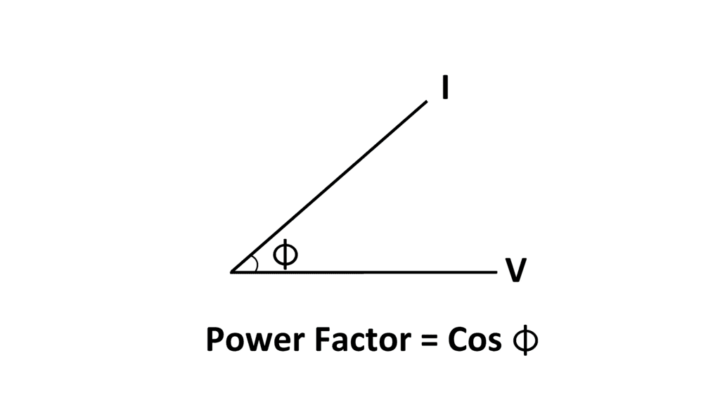
- Power factor = cos Φ = cosine of angle between V and I.
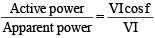
- Power factor

- Power factor
- Most of loads are inductive in nature and hence have low lagging p.f.
- The low p.f. is highly undesirable as it causes an increase in current, resulting in additional losses of active power in all the elements.
- Make power factor unity, if possible.
- Current lags to voltage in inductive circuit
- Current leads to voltage in capacitive circuit.

Power Triangle
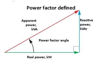
The power triangle is a graphical representation used in electrical engineering to illustrate the relationship between different types of power in an AC (alternating current) circuit. The three types of power represented in the power triangle are:
Real Power (P): This is the actual power consumed by the circuit to perform useful work, measured in watts (W). It is represented on the horizontal axis of the power triangle.
Reactive Power (Q): This is the power that oscillates between the source and the load, contributing to the establishment of electric and magnetic fields. It does not perform any useful work and is measured in volt-amperes reactive (VAR). It is represented on the vertical axis of the power triangle.
Apparent Power (S): This is the total power supplied to the circuit, combining both real and reactive power. It is measured in volt-amperes (VA) and is represented as the hypotenuse of the power triangle.
The power triangle is a right triangle where:
- The base (adjacent side) represents the real power (P).
- The perpendicular (opposite side) represents the reactive power (Q).
- The hypotenuse represents the apparent power (S).
The relationship between these powers can be expressed using the Pythagorean theorem:
- Active power = VI cos Φ kW
- Apparent power = VI kVA
- Reactive power = VI sin Φ kVAr
- Power Factor
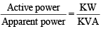
- Smaller the reactive power component, the higher is the p.f. of circuit
kVAr = kVA sinf
kVAr = kW tanf
- The Reactive power is neither consumed in the circuit nor it does any useful work. It nearly flow back and forth in both direction in the circuit.
- A watt meter does not measure reactive power.
Example
Let, Voltage = 200 V, current = 10A,
Power factor = cosf = 0.8 lagging
Then, Apparent power = VI = 200 × 10 = 2000 VA
and, Active power = VI cosf = 200 × 10 = 0.8 = 1600 W
Reactive power = VI sinf = 200 × 10 × 0.6 = 1200 VAR.
Analysis
- Here circuit receives 2000 VA and is able to convert only 1600 W, 1200 VAr does no useful work. It nearly flows into and out the circuit periodically.
Causes of Low Power Factor Low power factor is undesirable from economic point of view. Normally, the power factor of the whole load on the supply system is lower than 0.8.
Following Reason :
- Most of a.c. motors are induction type single phase and three phase which have low lagging p.f. (say 0.2 to 0.3) and rises to 0.8 to 0.9 at full load.
- Arc lamps, electric discharge lamps and industrial heating furnaces operate at low lagging power factor.
- The load on the power system is varying; being high during morning and evening and low at other times.
- During low load periods, supply voltage is increased which increases the magnetisation current. This results in the decreased power.
Disadvantages of Low Power Factor
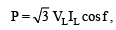
- Power for single phase circuit P = VLIL cos f,
- Line current in single phase circuit

- Power for three phase circuit
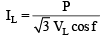
- Line current in three phase circuit
Try yourself: In an AC circuit where the voltage is 200V, current is 10A and the power factor is 0.8 lagging, what is the value of the reactive power?
Large kVA Rating of Equipment

- If kVA is large then equipment is large and expensive.
Greater Conductor Size
- To transmit or distribute a fixed amount of power at constant voltage, the conductor will have to carry more current at low power factor. This necessitates large conductor size.
Large Copper Losses
- I2R, because current is high.
Poor Voltage Regulation
- The large current at low lagging p.f. causes greater voltage drops in alternators, transformer, transmission lines and distributors. This result in the decreased voltage available at the supply end.
- For control it desired other equipment (voltage regulator).
Reduced handling capacity of system
- It is because the reactive component of current prevents the full utilisation of installed capacity. The capacitor draws leading current.
Power Factor Improvement
The capacitor draws a leading current.
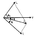
I cos f1 = I' cos f2
- The active component remains the same before and after p.f. correction because only the lagging reactive component's reduced by the capacitor.
- The lagging p.f. (Reactive component) is reduced after p.f.
I' sin f2 = I sinf - Ic (capacitor current)
but I cos f1 = I' cos f2
VI cos f1 = VI' cos f2
(No change in active power (KW) due to p.f. correction (improvement)
I' sinf2 = I sinf1 - Ic VI' sinf2 = VI sinf1 = VIc
Net KVAR after p.f. correction = lagging KVAR before p.f. correction leading KVAR of equipment
Power Factor Improvement Equipment
- Power factor can be improved by following equipments :
- Static capacitors.
- Synchronous condenser.
- Phase advancers.
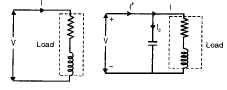
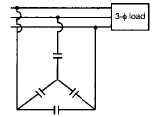
Static capacitor The power factor can be improved by connecting capacitors in parallel with the equipment operating at lagging p.f. The capacitor (generally known as static capacitor) draws a leading current.
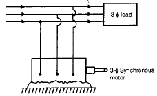
Synchronous condenser An over excited synchronous motor running on no-load is known as synchronous condenser. When such an electrical machine is connected in parallel with the supply it takes a leading current which partly neutralises the lagging reactive component of the load.
Thus the power factor is improved.
Advantages:
- By varying the field excitation, the magnitude of current drawn by the motor can be changed by any amount. This helps in achieving stepless control of power factor.
- The motor loads have high thermal stability to short circuit currents.
- The faults can be removed easily.
Disadvantages:
- There are considerable losses in the motor.
- The maintenance cost is high.
- Produces noise.
- As a synchronous motor has no self starting torque, therefore, an auxiliary equipment has to be provided for the purpose.
Note:
- The reactive power taken by a synchronous motor depends upon two factors, the d.c. field excitation the mechanical load delivered by the motor. Maximum leading power is taken by a synchronous motor with maximum excitation and zero load.
Phase Advancers
- Phase advancers are used to improve the p.f. of induction motors. The low p.f. of an induction motor is due to the fact that its stator draws exciting current which lags behind the supply voltage by 90°.
- If the phase advancer is mounted on the same shaft as the main motor is connected in the rotor circuit of motor. It provides exciting amp turns (I1N1) to the rotor circuit at slip frequency.
- By providing more, (I1N1) by exciter than required, the induction motor can be made to operate on leading p.f. like an over excited synchronous motor.
- More exiciting I1N1 are supplied at slip frequency therefore kVAr reduced which drawn by motor phase advancer.
- Advantage is conveniently used where synchronous motor is inadmissible.
Disadvantage:
- They are not economical for motors of rating below 200 H.P.
Importance of Power Factor Improvement For Consumers
- A consumer has to pay electricity charges of maximum demand in kVA + Unit consumed
- If p.f. is improved than maximum demand charges are reduced.
Annual Profit
- Reduced price in maximum demand Expenditure in improvement of p.f.
For generating station
- In generating station generation is in KVA but output in KW station output (KW = KVA cosf).
Note:
- No. of units supplied by it depend upon the p.f. If cosf, then kWh is improved which delivers to the system. This leads to the conclusion that improved power factor increases the earning capacity of the power station.
Most economical power factor The value to which the p.f. should be improved so as to have maximum net annual saving is known as the most economical power factor.
Try yourself: What are the disadvantages of a low power factor?
FAQs on Power Factor Improvement
| 1. What's the difference between leading and lagging power factor in electrical systems? |  |
| 2. How does adding capacitors improve power factor in a circuit? | |
| 3. Why is power factor correction important for industrial electrical systems? | |
| 4. What methods can be used for power factor improvement besides capacitor banks? | |
| 5. How do I calculate the capacitor size needed to achieve a target power factor? | |


 | Explore Courses for Electrical Engineering (EE) exam |
 | Get EduRev Notes directly in your Google search |