Bearings


Bearing
Bearing: The horizontal angle between a survey line and a reference meridian measured clockwise from the meridian to the line is called the bearing of the line. The reference meridian used in surveying may be one of the following:
- True meridian
- Magnetic meridian
- Grid meridian
- An arbitrary reference direction
Meridians and Directions
True Meridian
The true (geographical) meridian at a point on the Earth's surface is the line obtained by the intersection of the Earth's surface with a plane passing through the point and the true north and south poles.
Magnetic Meridian
The magnetic meridian at a place is the line along which a freely suspended magnetic needle normally points; it is the intersection of the Earth's surface with the plane through the place and the magnetic north and south poles.
True North and Magnetic North
- True north: direction towards the North Geographical Pole along the true meridian.
- Magnetic north: direction that the north end of a freely suspended magnetic needle points to at that place at the time of observation.
Most official topographic maps are prepared with reference to the true meridian.
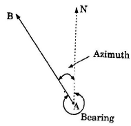
True and Magnetic Bearing; Azimuth
True bearing: The horizontal angle measured clockwise from the true north to the survey line. This is usually expressed in the whole circle bearing system (0° to 360°).
Magnetic bearing: The horizontal angle measured clockwise from the magnetic north to the survey line. Magnetic bearings may change with time because magnetic north changes slowly.
Azimuth: Commonly, azimuth is used as the same as the whole circle bearing measured clockwise from true north; its value lies between 0° and 360°. If required, the acute angle between the line and the meridian may be obtained from the azimuth by taking the smaller of the azimuth and its supplement to 360° (that is, min(azimuth, 360° - azimuth)).
Examples (azimuth/true bearing)
Example 1: If the true bearing of a line is 275°41′, then its azimuth (true bearing in W.C.B.) is 275°41′.
Solution.
Azimuth = 275°41′
Example 2: If the true bearing of a line is 30°45′ (less than 180°), then its azimuth is 30°45′.
Solution.
Azimuth = 30°45′
Bearing Designation Systems
Two common systems of designating bearings are:
- Whole Circle Bearing (W.C.B.)
- Quadrantal or Reduced Bearing (Q.B. or R.B.)
Whole Circle Bearing (W.C.B.)
In the W.C.B. system, bearings are measured clockwise from north through 0° to 360°. For example, a line having W.C.B. of 120° lies in the SE direction from its origin.
Quadrantal (Reduced) Bearing (Q.B. or R.B.)
In the quadrantal or reduced bearing system, the bearing of a line is given as an angle less than or equal to 90° measured eastward or westward from the nearer of north or south. Notation uses the form N a° E, S a° E, S a° W or N a° W, where a° is between 0° and 90°.
Conversion Between W.C.B. and Q.B. (R.B.)
To convert a W.C.B. to the corresponding Q.B., determine the quadrant in which the bearing lies and apply the appropriate rule.
| Case | W.C.B. between | Rule to get Q.B. (R.B.) | Quadrant |
|---|---|---|---|
| I | 0° to 90° | Q.B. = W.C.B. | N.E. |
| II | 90° to 180° | Q.B. = 180° - W.C.B. | S.E. |
| III | 180° to 270° | Q.B. = W.C.B. - 180° | S.W. |
| IV | 270° to 360° | Q.B. = 360° - W.C.B. | N.W. |
Special cases (line exactly on cardinal directions)
- If W.C.B. = 0°, the Q.B. is N (i.e., due North).
- If W.C.B. = 90°, the Q.B. is E (i.e., due East).
- If W.C.B. = 180°, the Q.B. is S (i.e., due South).
- If W.C.B. = 270°, the Q.B. is W (i.e., due West).
Worked conversion example
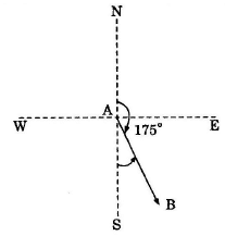
Example: Convert W.C.B. = 175° to Q.B.
Solution.
W.C.B. 175° lies between 90° and 180°, so it is in the S.E. quadrant.
Q.B. = 180° - 175° = 5°
Therefore the Q.B. is S 5° E.
Fore and Back Bearings
Every straight line has two bearings depending on direction of measurement:
- Fore (forward) bearing (F.B.): bearing measured in the direction of progress of survey.
- Back (reverse) bearing (B.B.): bearing measured in the opposite direction.
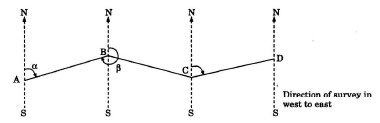
In the W.C.B. system, the back bearing differs from the fore bearing by 180°. The relation is:
Back bearing = Fore bearing ± 180°
Use +180° if the fore bearing is less than 180°; use -180° (or equivalently add 180° and reduce modulo 360°) if the fore bearing is 180° or greater.
Converting fore to back bearing in Q.B. system
To obtain the back bearing in Q.B. from the fore bearing in Q.B., replace N by S and S by N; replace E by W and W by E; keep the angle value unchanged. For example, if F.B. = N a° E then B.B. = S a° W.
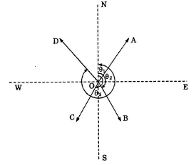
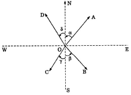
Included Angles from Bearings
The included angle at a station between two lines can be obtained from the bearings of the lines. The method depends on the bearing system used.
Using W.C.B.
If bearings of AB and AC measured from north are ÐNAB = a and ÐNAC = b (both W.C.B.), then the included angle ∠BAC is
∠BAC = |b - a|
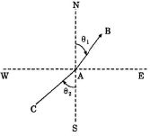
Using Q.B. (examples illustrated)
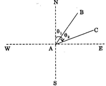
When both lines are in the same quadrant and measured from the same reference direction, the included angle = q2 - q1 (where q1 and q2 are the reduced angles).
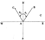
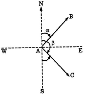
When lines are in adjacent quadrants with reference directions adding, included angle = q1 + q2.
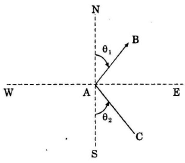
When lines are in opposite quadrants, included angle = 180° - (q2 - q1) (as appropriate to the geometry).
When geometry leads to an angle greater than 180° from calculation, take its supplement with 360° to obtain the smaller included angle (included angles are normally taken ≤ 180°).
Notes:
- In a closed traverse run anticlockwise, the observed included angles are the interior angles.
- In a closed traverse run clockwise, the observed included angles are the exterior angles.
- If a calculated included angle exceeds 180°, subtract it from 360° to get the conventional included angle (less than or equal to 180°).
Local Attraction
Local attraction is the disturbance of the direction of a magnetic needle caused by nearby magnetic influences such as iron or steel structures, electric currents in cables, magnetic ores, or other local magnetic anomalies. It causes the observed magnetic bearing to differ from the true magnetic direction at that location.
Detection of Local Attraction
Local attraction at a station may be detected by observing the fore and back bearings of the same line. If the difference between fore and back bearings is exactly 180°, there is no local attraction at either station (neglecting observational errors). If the difference is not 180°, the discrepancy may be due to one or more of the following:
- an observational error in the fore or back bearing (or both)
- presence of local attraction at one station
- presence of local attraction at both stations
Correction for Local Attraction
Common methods of correction are:
- Calculate included angles at affected stations from observed bearings of adjoining lines and compare with computed included angles from the traverse; adjust the bearings to satisfy geometric closure.
- Compute the local attraction correction at each station by comparing observed back bearings with the back bearings calculated from unaffected stations; apply the corrections to the observed magnetic bearings to obtain corrected magnetic bearings.
Always start corrections from stations known or assumed to be free from local attraction and proceed sequentially around the traverse.
Magnetic Declination (Magnetic Variation)
Magnetic declination (or magnetic variation) at a place and time is the horizontal angle between the true meridian and the magnetic meridian. It is positive when magnetic north lies east of true north and negative when magnetic north lies west of true north. Magnetic declination changes slowly with time and place and must be checked against current local values when converting between magnetic and true bearings.
Useful Geometric Relations for Traverses
- Sum of interior angles of an n-sided polygon = (n - 2) × 180°.
- Sum of exterior angles of any closed polygon, taken in the same sense, = 360°.
Final Remarks
Bearing routines in surveying require careful attention to the system in use (W.C.B. or Q.B.), consistent notation, and correction for local magnetic effects and observational errors. Always state which meridian and which bearing system has been used when recording or publishing bearings.
FAQs on Bearings
| 1. What are bearings in civil engineering? |  |
| 2. What are the different types of bearings used in civil engineering? | |
| 3. Why are bearings important in civil engineering structures? | |
| 4. How are bearings designed and installed in civil engineering projects? | |
| 5. What are the common problems and maintenance requirements for bearings in civil engineering? | |


