Laws of Motion Detailed Explanation | Physics Class 11 - NEET PDF Download
Force
A pull or push which changes or tends to change the state of rest or of uniform motion or direction of motion of an object is called Force.
Force is the interaction between the object and the source (providing the pull or push). It is a vector quantity. In this document vector quantities will be either denoted by bold letters like v or with bar on top  .
.
 Force: pull or push
Effect of Resultant Force
- May change only speed.
- May change only the direction of motion.
- May change both the speed and direction of motion.
- May change the size and shape of a body.
Unit of Force
- Newton (N) and
 (MKS System). 1 N =.
 - Dyne and (CGS System). 1 dyne =
- 1 newton = 105 dyne
 (MKS System). 1 N =
 .
. (CGS System). 1 dyne =
Kilogram Force (kgf)
- The force with which earth attracts a 1 kg body towards its centre is called kilogram force, thus,
kgf = - Dimensional Formula of force: [MLT-2]
- For full information of force we require:
→ Magnitude of force
→ direction of force
→ point of application of the force

Types of Forces
There are basically two types of forces which are commonly encountered in mechanics.

1. Field Forces or Non-Contact Forces
Non-contact forces are the forces in which contact between two objects is not necessary.
Gravitational force between two bodies and electrostatic force between two charges are two examples of field forces.
Weight (W = mg) of a body comes in this category.
2. Contact Forces
Contact force is a force that is applied by objects in contact with each other.
- If the contact is frictionless, the contact force is perpendicular to the common surface and known as Normal reaction.
- If, however, the objects are in rough contact and move (or have a tendency to move) relative to each other without losing contact then frictional force arise which oppose such motion. Again each object exerts a frictional force on the other and the two forces are equal and opposite. This force is perpendicular to normal reaction.
- Thus, the contact force ( F) between two objects is made up of two forces.
(i) Normal reaction (N) or (R)
(ii) Force of friction (f )
and since these two forces are mutually perpendicular the resultant force is given by the following formula:
 Consider two wooden blocks A and B being rubbed against each other.
In Figure shown below, A is being moved to the right while B is being moved leftward.

In order to see more clearly which forces act on A and which on B, a second diagram is drawn below showing a space between the blocks but they are still supposed to be in contact.

In Figure, the two normal reactions each of magnitude N are perpendicular to the surface of contact between the blocks and the two frictional forces each of magnitude fact along that surface, each in a direction opposing the motion of the block upon which it acts. We will read about Normal Reaction in detail later in the document.
Note: Forces on block B from the ground are not shown in the figure.
Newton’s Laws of Motion
Newton has published three laws, which describe how forces affect motion of a body on which they act. These laws are fundamental in nature in the sense that the first law gives concept of force, inertia and the inertial frames; the second law defines force and the third law action and reaction as two aspects of mutual interaction between two bodies.
The First Law
Every material body has tendency to preserve its state of rest, or of uniform motion in a straight line, unless it is compelled to change that state by external forces impressed on it.
- Inertia
The tendency of a material body to preserve its present state of uniform motion or of rest is known as inertia of the body. It was first conceived by Galileo.
Inertia is a physical quantity and mass of a material body is measure of its inertia. - Inertial Frame of Reference
The first law requires a frame of reference in which only the forces acting on a body can be responsible for any acceleration produced in the body and not the acceleration of the frame of reference. These frames of reference are known as inertial frames.
The Second Law
The rate of change in momentum of a body is equal to, and occurs in the direction of the net applied force.
A body of mass m in translational motion with velocity if acted upon with a net external force F the second law suggests:

If mass of the body is constant, the above equation relates the acceleration a of the body with the net force F acting on it.

The first law provides concept of force and the second law provides the quantitative definition of force, therefore the second law is also valid only in inertial frames.
SI unit of force is newton. It is abbreviated as N. One newton equals to one kilogram-meter per second square.
1 N = 1 kg-m/s2
Dimensions of force are MLT–2
The Third Law
Newton’s 3rd law of motion states that for every action, there is an equal and opposite reaction.
Force is always a two-body interaction. The first law describes qualitatively and the second law describes quantitatively what happens to a body if a force acts on it, but do not reveal anything about what happens to the other body participating in the interaction responsible for the force.
The third law accounts for this aspect of the force and states that every action on a body has equal and opposite reaction on the other body participating in the interaction.
Concept of Free Body Diagram (FBD)
What is the need for Free Body Diagram?
A force on a body can only exists when there is another body to create it, therefore in every physical situation of concern there must be two or more bodies applying forces on each other. On the other hand the three laws of Newton, describe motion of a single body under action of several forces, therefore, to analyze a given problem, we have to consider each of the bodies separately one by one. This idea provides us with the concept of free body diagram.
Definition - Free Body Diagram
A free body diagram is a pictorial representation in which the body under study is assumed free from rest of the system i.e. assumed separated from rest of the interacting bodies and is drawn in its actual shape and orientation and all the forces acting on the body are shown.
How to draw a Free Body Diagram (FBD)
1. Identify the Contact Forces.
2. After identifying the contact forces, draw a dot to represent the object that we are interested in. Here, we are only interested in determining the forces acting on our object.
3. Draw a coordinate system and label positive directions.
4. Draw the contact forces on the dot with an arrow pointing away from the dot. The arrow lengths should be relatively proportional to each other. Label all forces.
5. Draw and label our long-range forces. This will usually be weight unless there is an electric charge or magnetism involved.
6. If there is acceleration in the system, then draw and label the acceleration vector.
Various Field Forces
Field forces include the gravitational force (weight) electrostatic forces and magnetic forces, which can easily be identified. At present, we consider only gravitational pull from the earth i.e. weight of the body.
Weight: The net gravitational pull of the Earth
The gravitational pull from the earth acts on every particle of the body hence it is a distributed force. The net gravitational pull of the Earth on a body may be considered as weight of the body.

- It is assumed to act on the center of gravity of the body.
- For terrestrial bodies or celestial bodies of small size, this force can be assumed uniform throughout its volume. Under such circumstances, center of gravity and center of mass coincide and the weight is assumed to act on them. Furthermore, center of mass of uniform bodies lies at their geometrical center. At present, we discuss only uniform bodies and assume their weight to act on their geometrical center.
- In the figure shown above weight of a uniform block is shown acting on its geometrical centre that coincides with the center of mass and the centre of gravity of the body.
Various Contact Forces
At every point where a body under consideration is supposed to be separated from other bodies to draw its free-body diagram, there may be a contact force. Most common contact forces, which we usually encounter, are tension force of a string, normal reaction on a surface in contact, friction, spring force etc.
Tension Force of Strings
- We use a string or similar flexible connecting links as a thread or a chain etc. to transmit a force.
- Due to flexibility, a string can be used only to pull a body connected to it by applying a force always along the string.
- According to the third law, the connected body must also apply an equal and opposite force on the string, which makes the string taut. Therefore, this force is known as tension force T of the string.
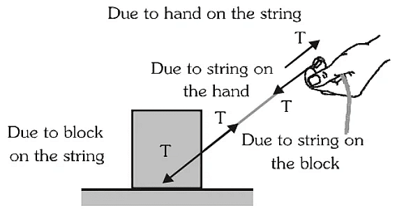
- In the given figure a block is shown. It is being pulled by a string, which is being pulled by a person.
- The tension force applied by string on the block and the force applied by the block on the string shown in the figure constitute a third law action-reaction pair. Similarly, tension force applied by the string on hand and force applied by the hand on string is another third law action-reaction pair.
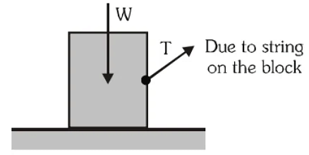
- While studying motion of the block, the force applied by the string on it, weight of the block and a reaction from the floor has to be considered. In the figure only weight and tension of string are shown.
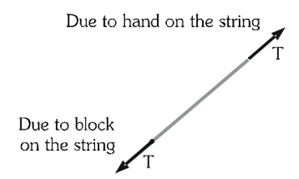
- To study motion of the string, the force applied by the block on the string and the force applied by the hand on the string must be considered. These forces are shown in the FBD of string.
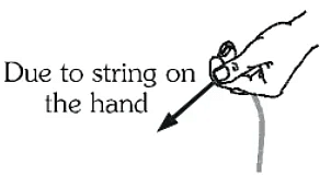
- To study conditions of motion of the person, the force applied by the string on the hand has to be considered as shown in the figure.
String passing over a pulley
A pulley is a device consisting of a wheel, which can rotate freely on its axel. A single pulley changes direction of tension force. At present for simplicity, we discuss only ideal pulley, which is massless i.e. has negligible mass and rotates on its axel without any friction. An ideal pulley offers no resistance to its rotation, therefore tension force in the string on both sides of it are equal in magnitude. Such a pulley is known as ideal pulley.

Normal Reaction
Two bodies in contact, when press each other, must apply equal and opposite forces on each other. These forces constitute a third law action-reaction pair. If surfaces of the bodies in contact are frictionless, this force acts along normal to the surface at the point of contact. Therefore, it is known as normal reaction.
Consider a block of weight W placed on a frictionless floor. Because of its weight it presses the floor at every point in contact and the floor also applies equal and opposite reaction forces on every point of contact. We show all of them by a single resultant N obtained by their vector addition.

 Normal Reaction
To apply Newton's laws of motion (NLM) on the block, its weight W and normal reaction N applied by the floor on the block must be considered as shown in the following figure. It is the FBD of the block.

Consider a spherical ball of weight W placed on a floor. The normal reaction from the floor on the ball and from the ball on the floor makes a third law action-reaction pair. These forces are shown in the left figure.

To apply Newton's laws of motion (NLM) on the ball, its weight W and normal reaction N applied by the floor on the ball must be considered as shown in the above right figure. It is the FBD of the ball.
When two surfaces make contact, the normal reaction acts along the common normal and when a surface and a sharp corner make a contact the normal reaction acts along the normal to the surface. Consider a block placed in a rectangular trough as shown in the figure.


To apply Newton's laws of motion (NLM) on the block, its free body diagram (FBD) is shown in the above right figure.
Spring Force
When no force acts on a spring, it is in relaxed condition i.e. neither compressed nor elongated. Consider a spring attached to a fixed support at one of its end and the other end is free. If we neglect gravity, it remains in relaxed state. When it is pushed by a force F, it is compressed and displacement x of its free end is called compression. When the spring is pulled by a force F, it is elongated and displacement x of its free end is called elongation. Various forces developed in these situations are shown in the following figure.
 Various cases of spring force
The force applied by the spring on the wall and the force applied by the wall on the spring make a third law action-reaction pair. Similarly, force by hand on the spring and the force by spring on the hand make another third law action-reaction pair.
Conservation of Momentum
Conservation of momentum is a major law of physics which states that the momentum of a system is constant if no external forces are acting on the system. It is embodied in Newton’s First Law or The Law of Inertia. The law of conservation of momentum is generously confirmed by experiment and can even be mathematically deduced on the reasonable presumption that space is uniform.
Conservation of Linear Momentum
Conservation of linear momentum is based on Newton’s second law of motion which states that in an isolated system the total momentum remains the same. Let’s consider the following example,

Remember: In the above experiment we did not consider any loss of energy due to friction, heat, etc. and all the collisions were elastic in nature i.e. there was a total transfer of energy, Actual observations may differ.
Let’s consider a case where a football of mass M2 is resting on the ground, a bowling ball with a comparatively heavier mass of M1 is thrown at the football at a velocity of U1.
When the bowling ball hits the football the energy is transferred and the bowling ball loses some velocity and moves at a new velocity V1, the football moves at velocity V2, why did the football move?
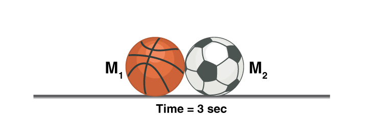
To conserve linear momentum, i.e. the bowling ball had an initial momentum of M1 so as M2 < M1 and the momentum of football should be equal to the momentum lost by the bowling ball according to the law of conservation of momentum, the football had no other option than moving at a velocity V2.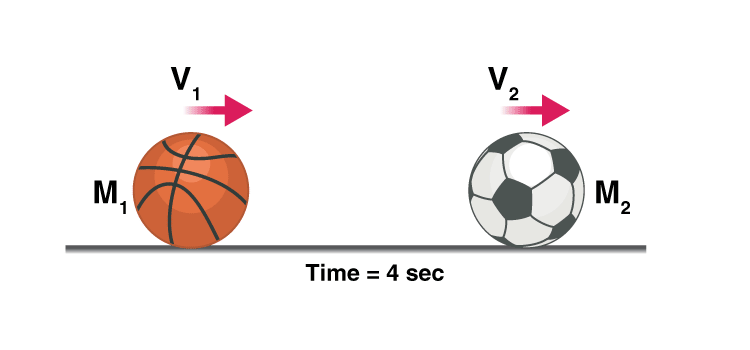
Formula
Mathematically it is given by,
m1u1 + m2u2 = m1v1 + m2v2
Note: m1u1 ≠ m1v1
Where,
m1 is mass of the bowling ball
m2 is the mass of the football
u1 and u2 are the initial velocities and v1 and v2 are the final velocities.
- Even though the momentum of each particle changes, altogether the momentum of the system remains constant as long as there is no external force acting on it.
- In a head-to-head car accident, the momentum is transferred from one car to the other, but so much force is applied that the car structure cannot handle it; this is why a car wrecks.
- If the cars were able to deal with the amount of force, and the collision was elastic, they both will move in opposite directions, considering their weights are the same.
- In short, momentum is always conserved in any collision, whether it be an elastic or a non-elastic collision.
- Though kinetic energy is not conserved in a non-elastic collision, the kinetic energy is converted into heat energy or potential energy, etc.
Example of Conservation Of Momentum
Consider this example of a balloon, the particles of gas move rapidly colliding with each other and the walls of the balloon, even though the particles themselves move faster and slower when they lose or gain momentum when they collide, the total momentum of the system remains the same.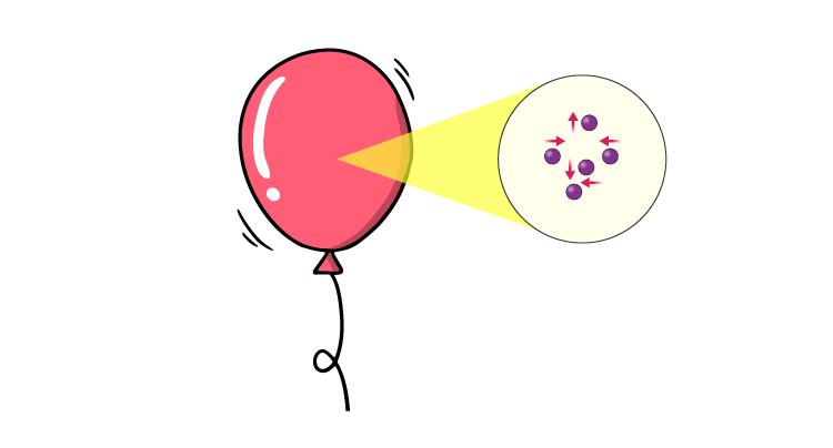 Hence, the balloon doesn’t change in size, if we add external energy by heating it, the balloon should expand because it increases the velocity of the particles and this increases their momentum, in turn, increasing the force exerted by them on the walls of the balloon.
Application of Law of Conservation of Momentum
Having said so the energy of a system is always conserved, one of the best applications of the law of conservation of momentum would be in space travel, there is no medium in space to exert a force on, then how do rockets travel?
Well, they eject matter at very high speed so in an isolated system the momentum should remain constant therefore the rocket will move in the opposite direction with the same momentum as that of the exhaust.
Equilibrium
Forces which have zero resultant and zero turning effect will not cause any change in the motion of the object to which they are applied. Such forces (and the object) are said to be in equilibrium. For understanding the equilibrium of an object under two or more concurrent or coplanar forces let us first discuss the resolution of force and moment of a force about some point.
Resolution of a Force
When a force is replaced by an equivalent set of components, it is said to be resolved. One of the most useful ways in which to resolve a force is to choose only two components (although a force may be resolved in three or more components also) which are at right angles also. The magnitude of these components can be very easily found using trigonometry.
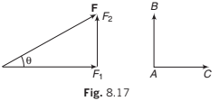
In Fig. 8.17, F1 = F cos θ = component of F along AC.
F2 = F sin θ = component of F perpendicular to AC AB.
Finding such components is referred to as resolving a force in a pair of perpendicular directions.
Note: that the component of a force in a direction perpendicular to itself is zero. For example, if a force of 10 N is applied on an object in horizontal direction then its component along vertical is zero. Similarly, the component of a force in a direction parallel to the force is equal to the magnitude of the force. For example component of the above force in the direction of force (horizontal) will be 10 N.
In the opposite direction the component is −10 N.
Example 8.4 Resolve a weight of 10 N in two directions which are parallel and
perpendicular to a slope inclined at 30° to the horizontal.
Solution: Component perpendicular to the plane
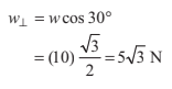
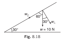
and component parallel to the plane
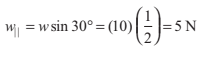
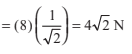
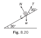
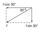
Example 8.5 Resolve horizontally and vertically a force F N = 8 which makes
an angle of 45° with the horizontal.
Solution Horizontal component of F is
= 4√2 N
and vertical component of F is FV = ° sin 45
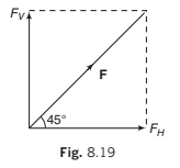
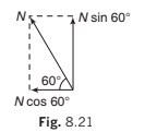
Example 8.6 A body is supported on a rough plane inclined at 30° to the horizontal by a string attached to the body and held at an angle of 30° to the plane. Draw a diagram showing the forces acting on the body and resolve each of these forces
(a) horizontally and vertically,
(b) parallel and perpendicular to the plane.
Solution. The forces are:
(i) The tension in the string T
(ii) The normal reaction with the plane N
(iii) The weight of the body w and the friction f
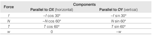
(a) Resolving horizontally and vertically
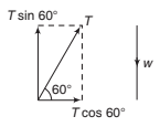
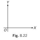
Resolving horizontally and vertically in the senses OX and OY as shown, the components are
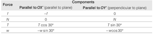
(b) Resolving parallel and perpendicular to the plane
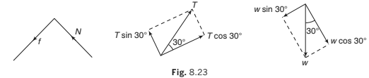
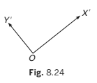
Resolving parallel and perpendicular to the plane in the senses OX ′ and OY ′ as shown, the components are :
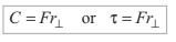
Moment of a Force
The general name given to any turning effect is torque. The magnitude of torque, also known as the moment of a force F is calculated by multiplying together the magnitude of the force and its perpendicular distance  from the axis of rotation. This is denoted by C or π (tau). i.e
Direction of Torque
The angular direction of torque is the sense of the rotation it would cause.
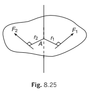
Consider a lamina that is free to rotate in its own plane about an axis perpendicular to the lamina and passing through a point A on the lamina. In the diagram, the moment about the axis of rotation of the force F1 is F1 r1 anticlockwise and the moment of the force F2
is F2r2 clockwise. A convenient way to differentiate between clockwise and anticlockwise torques is to allocate a positive sign to one sense (usually, but not invariably, this is anticlockwise) and a negative sign to the other. With this convention, the moments of F1
and F2 are + F1r1 and −F2 r2 (when using a sign convention in any problem it is advisable to specify the chosen positive sense).
Zero Moment
If the line of action of a force passes through the axis of rotation, its perpendicular distance from the axis is zero. Therefore, its moment about that axis is also zero.
Note: Later in the chapter of rotation we will see that torque is a vector quantity.
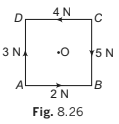
Example 8.7 ABCD is a square of side 2 m and O is its centre. Forces act along the sides as shown in the diagram.
Calculate the moment of each force about
(a) an axis through A and perpendicular to the plane of square.
(b) an axis through O and perpendicular to the plane of square.
Solution. Taking anticlockwise moments as positive we have:
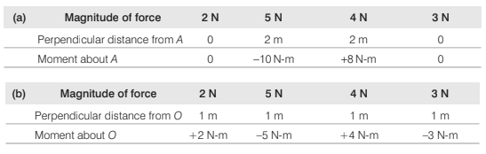
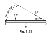
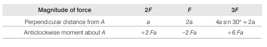
Example 8.8 Forces act as indicated on a rod AB which is pivoted at A. Find
the anticlockwise moment of each force about the pivot.
Solution.
Coplanar Forces in Equilibrium
When an object is in equilibrium under the action of a set of two or more coplanar forces, each of three factors which comprise the possible movement of the object must be zero, i.e. the object has
(i) no linear movement along any two mutually perpendicular directions OX and OY.
(ii) no rotation about any axis.
The set of forces must, therefore, be such that
(a) the algebraic sum of the components parallel to OX is zero or ∑Fx = 0
(b) the algebraic sum of the components parallel to OY is zero or ΣFy = 0
(c) the resultant moment about any specified axis is zero or Στany axis = 0
Thus, for the equilibrium of a set of two or more coplanar forces

Using the above three conditions, we get only three set of equations. So, in a problem number of unknowns should not be more than three.
Example 8.9 A rod AB rests with the end A on rough horizontal ground and the end B against a smooth vertical wall.
The rod is uniform and of weight w. If the rod is in equilibrium
in the position shown in figure. Find
(a) frictional force at A
(b) normal reaction at A
(c) normal reaction at B.

Solution Let length of the rod be 2l. Using the three conditions of
equilibrium. Anticlockwise moment is taken as positive.
(i) ΣFX = 0 ⇒ ∴ NB- fA − = 0
or NB =fA = ...(i)
(ii) ΣFY = 0 ⇒ ∴ NA − w = 0
or NA = w ... (ii)

(iii) ΣτO = 0
∴ NA(2l cos 30° ) - NB ( 2Isin 30° ) - w (l cos 30° ) = 0
or  ...(iii)
Solving these three equations, we get

Equilibrium of Concurrent Coplanar Forces
If an object is in equilibrium under two or more concurrent coplanar forces the algebraic sum of the components of forces in any two mutually perpendicular directions OX and OY should be zero, i.e. the set of forces must be such that
(i) the algebraic sum of the components parallel to OX is zero, i.e. ΣFx = 0.
(ii) the algebraic sum of the components parallel to OY is zero, i.e. ΣFy = 0.
Thus, for the equilibrium of two or more concurrent coplanar forces

The third condition of zero moment about any specified axis is automatically satisfied if the moment is taken about the point of intersection of the forces. So, here we get only two equations. Thus, number of unknown in any problem should not be more than two.
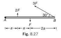
Example 8.10 An object is in equilibrium under four concurrent forces in the
directions shown in figure. Find the magnitudes of F1 and F2.

Solution: The object is in equilibrium. Hence,
(i) ΣFx = 0
∴ 8 + 4cos 60°- F2 cos 30°
or 
or 

(ii) ΣFy = 0
F1+ 4sin 60°− F2 sin 30° = 0
or 
or 
or 
Lami’s Theorem
If an object O is in equilibrium under three concurrent forces F1, F2 and F3 as shown in figure. Then,


This property of three concurrent forces in equilibrium is known as Lami’s theorem and is very useful method of solving problems related to three concurrent forces in equilibrium.
Example 8.11 One end of a string 0.5 m long is fixed to a point A and the other end is fastened to a small object of weight 8 N. The object is pulled aside by a horizontal force F, until it is 0.3 m from the vertical through A. Find the magnitudes of the tension T in the string and the force F.

Solution AC = 0.5 m, BC = 0.3 m
∴ AB = 0.4 m
and if ∠BAC= θ.
Then

Here, the object is in equilibrium under three concurrent forces.
So, we can apply Lami’s theorem.

or 
∴ 
Example 8.12 The rod shown in figure has a mass of 2 kg and length 4 m. In equilibrium, find the hinge force (or its two components) acting on the rod and tension in the string. Take g = 10m/s2. 

Solution

In the figure, only those forces which are acting on the rod has been shown. Here H and V are horizontal and vertical components of the hinge force.

Σ Fx = 0 ⇒ H T − = 0.8 0 ...(i)
Σ Fy = 0 ⇒ V + 0.6T − 20 = 0 ...(ii)
ΣτO = 0
⇒ Clockwise torque of 20 N = anticlock-wise torque of 0.6 T.
All other forces ( , H V and 0.8 T pass through O, hence their torques are zero).
∴ 20 × 2 = 0.6T X 4(iii)
Solving these three equations, we get
T = 16.67 N,
H = 13.33 N
and V = 10 N
Hinge force (F)
 Ans.
Ans.
∴  Ans.
Ans.
Applications
Motion of a Block on a Horizontal Smooth Surface
When Subjected to a Horizontal Pull
The distribution of forces on the body are shown. As there is no motion along vertical direction, hence, R = mg
For horizontal motion F = ma or a = F/m

When Subjected to a Pull acting at an Angle (θ) to the Horizontal
Now F has to be resolved into two components, F cosθ along the horizontal and F sinθ along the vertical direction.

For no motion along the vertical direction.
we have R F sinθ = mg
or R = mg -F sinθ
- : Hence R ¹ mg. R < mg
For horizontal motion
F cosθ = ma, a = 
When the Block is Subjected to a Push Acting at an Angle θ to the Horizontal (Downward)
The force equation in this case
R = mg F sinθ
- : R ¹ mg, R > mg
For horizontal motion
F cosθ = ma, a = 
Motion of Bodies In Contact
Two Body System
Let a force F be applied on mass m1

Free body diagrams:
(vertical force do not cause motion, hence they have not been shown in diagram)
⇒ a =  and f =
(i) Here f is known as force of contact.
(ii) Acceleration of system can be found simply by
a = 
: If force F be applied on m2, the acceleration will remain the same, but the force of contact will be different
i.e., f' = 
Ques 6: Find the contact force between the 3 kg and 2kg block as shown in figure.

Ans: Considering both blocks as a system to find the common acceleration
Fnet = F1 -F2 = 100 -25 = 75 N
common acceleration

To find the contact force
between A & B we draw
F.B.D of 2 kg block
from (åFnet)x = max
⇒ N -25 = (2) (15)
⇒ N = 55 N
Three Body System

Free body diagrams:
⇒ a = 
and f1 = 
f2 = 
f1 = contact force between masses m1 and m2
f2 = contact force between masses m2 and m3
Remember: Contact forces will be different if force F will be applied on mass C
Ques 7: Find the contact force between the block and acceleration of the blocks as shown in figure.

Ans: Considering all the three block as a system to find the common acceleration
Fnet = 50 -30 = 20 N


To find the contact force
between B & C we draw F.B.D.
of 3 kg block.

⇒ N1 -30 = 3(2) ⇒ N1 = 36 N
To find contact force between A & B we draw
F.B.D. of 5 kg block
⇒ N2 -N1 = 5a
N2 = 5 × 2 36 ⇒ N2 = 46 N
Motion of connected Bodies
For Two Bodies
F is the pull on body A of mass m1. The pull of A on B is exercised as tension through the string connecting A and B. The value of tension throughout the string is T only.

Free body diagrams :

⇒ a = 
Case (ii) : For Three bodies:

Free body diagrams:

⇒ a = 
Ques 8: A 5 kg block has a rope of mass 2 kg attached to its underside and a 3 kg block is suspended from the other end of the rope. The whole system is accelerated upward is 2 m/s2 by an external force F0.

(a) What is F0?
(b) What is the force on rope?
(c) What is the tension at middle point of the rope?
(g = 10 m/s2)
Ans: For calculating the value of F0, consider two blocks with the rope as a system.
F.B.D. of whole system
(a) 
F0 -100 = 10 × 2
F = 120 N ...(1)
(b) According to Newton's second law, net force on rope.
F = ma = (2) (2) = 4 N ...(2)
(c) For calculating tension at the middle point we draw F.B.D. of 3 kg block with half of the rope (mass 1 kg) as shown.
T -4g = 4.(2) = 48 N
Motion of a body on a smooth inclined plane:
Natural acceleration down the plane = g sinθ
Driving force for acceleration a up the plane, F=m(a gsinθ)
and for an acceleration a down the plane, F=m(a -gsinθ)

Ques 9: Find out the contact force between the 2kg & 4kg block as shown in figure.

Ans: On an incline plane acceleration of the block is independent of mass. So both the blocks will move with the same acceleration (gsin 37º) so the contact force between them is zero.
Ques 10: Find out the contact force between 2kg & 3kg block placed on the incline plane as shown in figure.

Ans: Considering both the block as a 5 kg system because both will move the same acceleration.

Now show forces on the 5 kg block:

 Acceleration of 5 kg block is down the incline.
So choose one axis down the incline and other
perpendicular to it
From Newton's second Law
N = 5g cos 37º ...(i)
5gsin 37º -20 = 5a ..(ii)
30 -20 = 5a
a = 2m/s2 (down the incline)
For contact force (N1) between 2 kg & 3 kg block
we draw F.B.D. of 3 kg block
From
Fnet = ma
⇒ 3 g sin 37º -N1 = 3 × 2
18 -N1 = 6
N1= 12 N
Pulley Block System
Ques 11: One end of string which passes through pulley and connected to 10 kg mass at other end is pulled by 100 N force. Find out the acceleration of 10 kg mass. (g = 9.8 m/s2)
Ans: Since string is pulled by 100N force.
So tension in the string is 100 N.
F.B.D. of 10 kg block
100 -10 g = 10 a
100 -10 × 9.8 = 10 a
a = 0.2 m/s2
Ques 12: In the figure shown, find out acceleration of each block.

Ans: Now F.B.D. of each block and apply Newton's second law on each F.B.D
(1) ⇒ 10g -2 T = 10a1 ...(i)
(2)  ⇒ T -2g = 2a2 ...(2)
(3) ⇒ T -4g = 4a3 ...(3)
from constrain relation 2a1 = a2 + a3 ...(4)
Solving equations (1), (2), (3) and (4) we get
T = 
a1 = 70/23 m/s2 (downward), a2 = 170/23 m/s2 (upward), a3 = 30/23 m/s2 (downward)
Ques 13: Find the acceleration of each block in the figure shown below; in terms of their masses m1, m2 and g. Neglect any friction.

Ans: Let T be the tension in the string that is assumed to be massless.
For mass m1, the FBD shows that
N1 = m1g
Where N1 is the force applied upward by plane on the mass m1.
If acceleration of m1 along horizontal is a1. then
T = m1a1 ...(i)
For mass m2, the FBD shows that
m2g -2T = m2a2 ...(ii)
Where a2 is vertical acceleration of mass m2.
Note that upward tension on m2 is 2T applied by both sides of the string.
from constrain relation
a2 = 
Thus, the acceleration of m1 its twice that of m2.
with this input, solving (i) and (ii) we find
a1 = 
a2 = 
Ques 14: Two blocks A and B each having a mass of 20 kg, rest on frictionless surfaces as shown in the figure below. Assuming the pulleys to be light and frictionless, compute:
(a) the time required for block A, to move down by 2m on the plane, starting from rest,
(b) tension in the string, connecting the blocks.

Ans:
Step 1: Draw the FBDs for both the blocks. If tension in the string is T, then we have
 and
and
Note that mAg, should better be resolved along and perpendicular to the plane, as the block A is moving along the plane.

Step 2: From FBDs, we write the force equations `
for block A where
NA = mA g cosθ = 20 × 10 × 0.8 = 160 N
and mAg sinθ -T = mA a ... (i)
Where `a' is acceleration of masses of blocks A and B. Similarly, force equations for block B are
NB = mBg = 20 × 10 = 200 N
and T = mBa ...(ii)
From (i) and (ii), we obtain
a =  =
=  = 3 ms-2
T = mBa = 20 × 3 = 60 N
Step 3: With constant acceleration a = 3 ms-2, the block A moves down the inclined plane a distance S = 2 m in time t given by
S =  or t =
Ques 15: Two blocks m1 and m2 are placed on a smooth inclined plane as shown in figure. If they are released from rest.
Find:
(i) acceleration of mass m1 and m2
(ii) tension in the string
(iii) net force on pulley exerted by string
Ans: F.B.D of m1 :
m1g sinθ -T = m1a
 -T =
-T =  ...(i)
F.B.D. of m2 :
T -m2g sinθ = m2a
T -1. = 1.a ...(ii)
Adding eq. (i) and (ii) we get a = 0
Putting this value in eq. (i) we get
T =  ,
,
F.B.D. of pulley
FR = 
FR = 
Ques 16: A block of mass `m' is kept on the ground as shown in figure.
(i) Draw F.B.D. of block
(ii) Are forces acting on block action - reaction pair
(iii) If answer is no, draw action reaction pair.
Ans: (i) F.B.D. of block

(ii) `N' and Mg are not action - reaction pair. Since pair act on different bodies, and they are of same nature.
(iii) Pair of `mg' of block acts on earth in opposite direction.

and pair of `N' acts on surface as shown in figure.

Climbing on the Rope

Now three condition arises.
if T > mg ⇒ man accelerates in upward direction
T < mg ⇒ man accelerates in downward direction
T = mg ⇒ man's acceleration is zero
Either climbing or descending on the rope man exerts force downward
Ques 17 If the breaking strength of string is 600N then find out the maximum acceleration of the man with which he can climb up the road
Ans: Maximum force that can be exerted on the man by the rope is 600 N.
F.B.D of man
⇒ 600 -50 g = 50 a
amax = 2 m/s2
⇒ 600 -50 g = 50 a
amax = 2 m/s2
Ques 18: A 60 kg painter on a 15 kg platform. A rope attached to the platform and passing over an overhead pulley allows the painter to raise himself along with the platform.

(i) To get started, he pulls the rope down with a force of 400 N. Find the acceleration of the platform as well as that of the painter.
(ii) What force must he exert on the rope so as to attain an upward speed of 1 m/s in 1 s?
(iii) What force should apply now to maintain the constant speed of 1 m/s?
Ans: The free body diagram of the painter and the platform as a system can be drawn as shown in the figure. Note that the tension in the string is equal to the force by which he pulled the rope.
(i) Applying Newton's Second Law
2T -(M m)g = (M m)a
or a = 
Here M = 60 kg; m = 15 kg ; T = 400 N
g = 10 m/s2
a =  = 0.67 m/s2
(ii) To attain a speed of 1 m/s in one second the acceleration a must be 1 m/s2
Thus, the applied force is
F =  (M m) (g a) = (60 15) (10 1) = 412.5 N
(iii) When the painter and the platform move (upward) together with a constant speed, it is in a state of dynamic equilibrium
Thus, 2F -(M m) g = 0
or F =  = 375 N
Spring Force
Every spring resists any attempt to change its length; when it is compressed or extended, it exerts force at its ends. The force exerted by a spring is given by F = -kx, where x is the change in length and k is the stiffness constant or spring constant (unit Nm-1)
When spring is in its natural length, spring force is zero.


(a) If block `A' and `B' both are displaced by 0.5 m in same direction.
(b) If block `A' and `B' both are displaced by 0.5 m in opposite d.
Pseudo Force
Before studying the concept of pseudo force let us first discuss frame of reference.Frame of reference is the way of observation the things.
Inertial Frame of Reference
A non-accelerating frame of reference is called an inertial frame of reference. A frame of reference moving with a constant velocity is an inertial frame of reference.
Non-inertial Frame of Reference
An accelerating frame of reference is called a non-inertial frame of reference.
Note: (i) A rotating frame of reference is a non-inertial frame of reference, because it is also an accelerating one.
(ii) Earth is rotating about its axis of rotation and it is revolving around the centre of sun also. So, it is non-intertial frame of reference. But for most of the cases, we consider its as an inertial frame of reference. Now let us come to the pseudo force. Instead of ground (or inertial frame of reference) when we start watching the objects from a non-inertial (accelerating) frame of reference its motion conditions are felt differently.
For example: Suppose a child is standing inside an accelerating lift. From ground frame of reference this child appears to be accelerating but from lift (non-inertial) frame of reference child appears to be at rest. To justify this changed condition of motion, from equations point of view we have to apply a pseudo force. This pseudo force is given by

Here, ‘m’ is the mass of that body/object which is being observed from non-inertial frame of reference and a is the acceleration of frame of reference. Negative sign implies that direction of pseudo force Fp is opposite to a. Hence whenever you make free body diagram of a body from a non-inertial frame, apply all real forces (actually acting) on the body plus one pseudo force. Magnitude of this pseudo force is ‘ma’ and the direction is opposite to a.
Example: Suppose a block A of mass m is placed on a lift ascending with an acceleration a0. Let N be the normal reaction between the block and the floor of the lift. Free body diagram of A in ground frame of reference (inertial) is shown in Fig. 8.100.
∴ 
But if we draw the free body diagram of A with respect to the elevator (a non-inertial frame of reference) without applying the pseudo force, as shown in Fig. 8.101, we get

or N mg ′ = ...(ii)
Since, N ≠ N, either of the equations is wrong. If we apply a pseudo force in non-inertial frame of reference, N ′ becomes equal to N as shown in Fig. 8.102.
Acceleration of block with respect to elevator is zero.
∴ N'- mg - ma0 = 0
or N' m= (g + a0) ...(iii)
∴ N' = N

Example 8.24 All surfaces are smooth in following figure. Find F, such that block remains stationary with respect to wedge.

Solution Acceleration of (block + wedge) 
Let us solve the problem by both the methods. Such problems can be solved with or without using the concept of pseudo force.
From Inertial Frame of Reference
FBD of block w.r.t. ground (Apply real forces):
With respect to ground block is moving with an acceleration a.
∴ ΣFy = 0
⇒ N mg cos θ = ...(i)
and ΣFx = ma
⇒ N sin θ = ma...(ii)

From Eqs. (i) and (ii), we get
a = g tan θ
∴ F= (M+ m)a
= (M+ m) g tan θ
From Non-inertial Frame of Reference (Wedge)

FBD of block w.r.t. wedge (real forces + pseudo force) w.r.t. wedge, block is stationary
∴ ΣFy = 0 ⇒ N mg cos θ = ...(iii)
ΣFx = 0 ⇒ N ma sin θ = ...(iv)
From Eqs. (iii) and (iv), we will get the same result
i.e. F= (M+ m) g tan θ
Example 8.25 A bob of mass m is suspended from the ceiling of a train moving with an acceleration a as shown in figure. Find the angle θ in equilibrium position.

Solution This problem can also be solved by both the methods.
Inertial Frame of Reference (Ground)
FBD of bob w.r.t. ground (only real forces)

With respect to ground, bob is also moving with an acceleration a.
∴ ΣFx = 0 ⇒ T ma sin θ = ...(i)
and ΣFy = 0 ⇒ T mg cos θ = ...(ii)
From Eqs. (i) and (ii), we get

Non-inertial Frame of Reference (Train)
FBD of bob w.r.t. train (real forces + pseudo force):

with respect to train, bob is in equilibrium
∴ ΣFx = 0
⇒ T sin θ = ...(iii)
∴ ΣFy = 0
⇒ T cos θ = ...(iv)
From Eqs. (iii) and (iv), we get the same result, i.e.

|
97 videos|378 docs|103 tests
|
FAQs on Laws of Motion Detailed Explanation - Physics Class 11 - NEET
| 1. What are the different types of forces in physics? |  |
| 2. What are Newton’s Laws of Motion? | |
| 3. What is a Free Body Diagram (FBD) and how is it used? | |
| 4. How do you determine the equilibrium of coplanar forces? | |
| 5. What is Lami's Theorem and how is it applied? | |

|
6.6K Views |

|
4.79/5 Rating |

|
Dec 22, 2024 Last updated |

|
Explore Courses for NEET exam
|
|
Exam
,Laws of Motion Detailed Explanation | Physics Class 11 - NEET
,Objective type Questions
,shortcuts and tricks
,Semester Notes
,study material
,ppt
,Previous Year Questions with Solutions
,Important questions
,Summary
,Sample Paper
,past year papers
,Laws of Motion Detailed Explanation | Physics Class 11 - NEET
,mock tests for examination
,Laws of Motion Detailed Explanation | Physics Class 11 - NEET
,Free
,MCQs
,practice quizzes
,video lectures
,Viva Questions
,Extra Questions
;


Detailed Explanation: Laws of Motion Free PDF Download
Importance of Detailed Explanation: Laws of Motion
Detailed Explanation: Laws of Motion Notes
Detailed Explanation: Laws of Motion NEET Questions
Study Detailed Explanation: Laws of Motion on the App
|
© EduRev
|
Education Revolution
|


|


