Capacitors


Capacitors and Capacitance
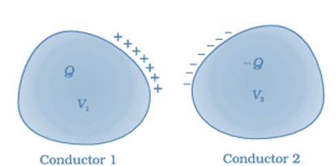 A system of two conductors separated by an insulator forms a capacitor
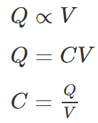
A capacitor is an arrangement of two or more conductors that can store electric charge and energy in the electric field between them. When conducting plates are given charges q1 and q2 (for example +q and -q), an electric field develops in the region between the plates. The potential difference V between the plates is related to the electric field, and the constant of proportionality between stored charge and potential difference is called the capacitance.
- Capacitance is defined as the ratio of the magnitude of charge on either conductor to the potential difference between them: C = Q / V.
- Unit of capacitance is farad in SI units and its dimensional formula is [M-1L-2T4I2]
- Although the formula suggests dependence on Q and V, the capacitance of a capacitor is a geometrical and material property: it depends on the shapes and sizes of the conductors and on the dielectric material placed between them.
Note:
- The net charge on the capacitor as a whole is zero. When we say that a capacitor has a charge Q, we mean that the positively charged conductor has charge +Q and negatively charged conductor has a charge, -Q.
- In a circuit a capacitor is represented by the symbol:
Standard units of capacitance
The SI unit of capacitance is the farad (F). Because 1 F is very large for most practical electronic components, submultiples are commonly used:
- 1 mF (millifarad) = 10-3 F
- 1 μF (microfarad) = 10-6 F
- 1 nF (nanofarad) = 10-9 F
- 1 pF (picofarad) = 10-12 F
Applications of Capacitors
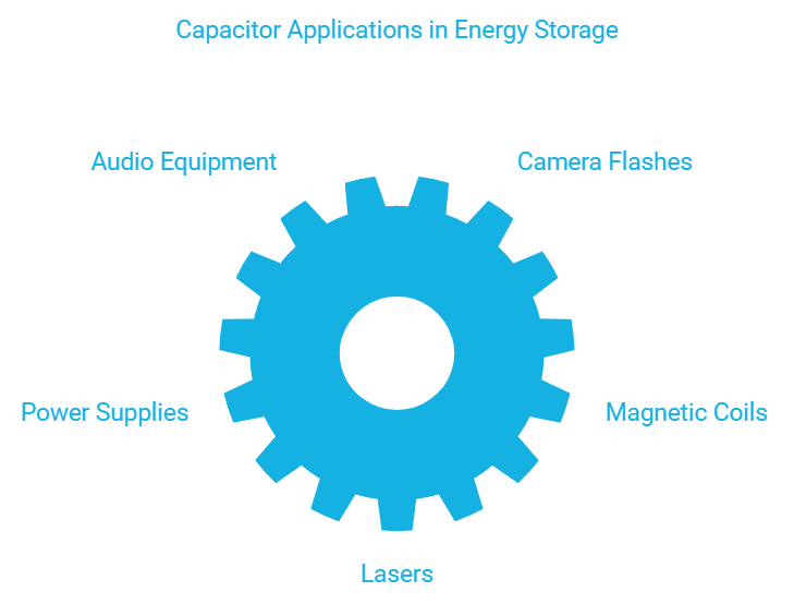
1. Capacitors for Energy Storage
Since the late 18th century, capacitors are used to store electrical energy. Individual capacitors do not hold a great deal of energy, providing only enough power for electronic devices to use during temporary power outages or when they need additional power. There are many applications that use capacitors as energy sources and a few of them are as follows: Audio equipment, Camera Flashes, Power supplies, Magnetic coils, Lasers
Supercapacitors are capacitors that have high capacitances up to 2kF. These capacitors store large amounts of energy and offer new technological possibilities in areas such as electric cars, regenerative braking in the automotive industry and industrial electrical motors, computer memory backup during power loss, and many others.
2. Capacitors for Power Conditioning
One of the important applications of capacitors is the conditioning of power supplies. Capacitors allow only AC signals to pass when they are charged blocking DC signals. This effect of a capacitor is majorly used in separating or decoupling different parts of electrical circuits to reduce noise, as a result of improving efficiency. Capacitors are also used in utility substations to counteract inductive loading introduced by transmission lines.
3. Capacitors as Sensors
Capacitors are used as sensors to measure a variety of things including humidity, mechanical strain, and fuel levels. Two aspects of capacitor construction are used in the sensing application - the distance between the parallel plates and the material between them. The former is used to detect mechanical changes such as acceleration and pressure and the latter is used in sensing air humidity.
4. Capacitors for Signal Processing
There are advanced applications of capacitors in information technology. Capacitors are used by Dynamic Random Access Memory (DRAM) devices to represent binary information as bits. Capacitors are also used in conjunction with inductors to tune circuits to particular frequencies, an effect exploited by radio receivers, speakers, and analog equalizers.
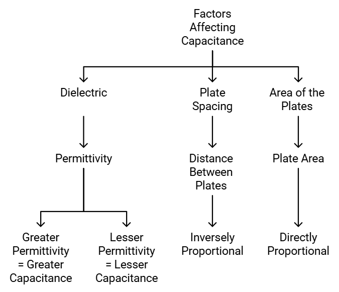
Factors Affecting Capacitance
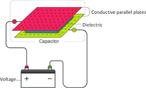
1. Dielectric
The effect of dielectric on capacitance is that the greater the permittivity of the dielectric the greater the capacitance, likewise lesser the permittivity of the dielectric the lesser is the capacitance. Some materials offer less opposition to the field flux for a given amount of field force. Materials with greater permittivity allow more field flux, hence greater charge is collected.
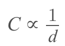
2. Plate Spacing
The effect of spacing on the capacitance is that it is inversely proportional to the distance between the plates. Mathematically it is given as:
3. Area of the Plates
The effect of the area of the plate is that the capacitance is directly proportional to the area. The larger the plate area more is the capacitance value. Mathematically, it is given as C ∝ A.
 Factors Affecting Capacitance
Capacitance of an Isolated Conductor
When a conductor is charged its potential increases. It is found that for an isolated conductor (finite-sized conductor so that potential at infinity is zero) potential of the conductor is directly proportional to the charge given to it.
q = charge on conductor
V = potential of conductor
q = CV
Where C is a proportionally constant called the capacitance of the conductor.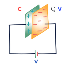
Capacitance of an isolated conductor depends on the following factors:
- Shape and size of the conductor
On increasing the size, capacitance increase. - In the surrounding medium
As the dielectric constant K increases, capacitance increases. - Presence of other conductors
When a neutral conductor is placed near a charged conductor capacitance of conductors increases.
Capacitance of a conductor does not depend on:
1. Charge on the conductor
2. Potential of the conductor
3. The potential energy of the conductor
Example. Find out the capacitance of an isolated spherical conductor of radius R.
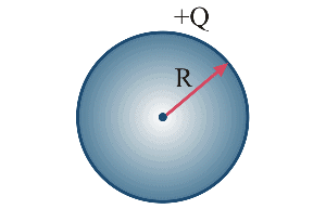
Sol. Let there is charge Q on the sphere.
Therefore, Potential V = KQ/R
Hence by the formula: Q = CV
Q = CV = (KQ)/R
C = 4πε0R
- If the medium around the conductor is a vacuum or air
Cvacuum = 4πε0R
R = Radius of the spherical conductor. (whether solid or hollow) - If the medium around the conductor is a dielectric of constant K from the surface of a sphere to infinity, then
Cmedium = 4πε0KR 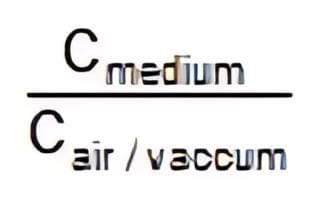 = K = dielectric constant
Parallel-plate capacitor
 Parallel Plate Capacitor
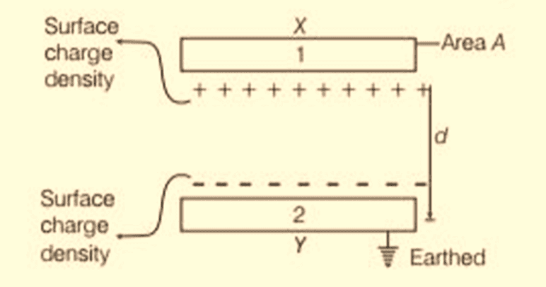
- Consider two identical conducting plates of area A separated by a small distance d (d ≪ √A) with vacuum or a dielectric between them.
- When a potential difference V is applied, the plates acquire charges +Q and -Q and store energy in the electric field between them.
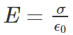
- The surface charge density on the plates is σ = Q / A.
- For small separations, the electric field between the plates is nearly uniform and its magnitude (for vacuum) is E = σ / ε0.
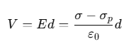
- The potential difference between the plates is V = E d.
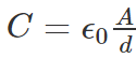
- Using Q = σA and V = (σ / ε0) d, the capacitance of a parallel-plate capacitor is

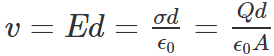
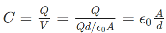
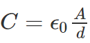
The familiar result is C = ε0 A / d for a parallel-plate capacitor with vacuum between plates.
Example 1: Calculate the capacitance of an empty parallel-plate capacitor that has metal plates with an area of 1.00 m2, separated by 1.00 mm.
Sol:
Using C = ε0A/d.
Substituting the values, we obtain the numerical value of the capacitance.

Effect of a dielectric on a parallel-plate capacitor
When a dielectric slab fully occupies the space between the plates, the dielectric becomes polarised in the presence of the electric field. The bound surface charge densities of the dielectric reduce the net field in the medium.
The field inside the dielectric is equivalent to that produced by net surface charge densities ±(σ - σp) on the plates, where σ is the free charge density and σp is the bound (polarisation) surface charge density produced in the dielectric.
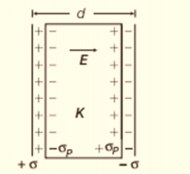 Dielectric between the plates of a capacitor
Therefore, the net electric field between the plates becomes

Because the dielectric polarisation is opposite to the external field, the potential difference between the plates is reduced:
For linear dielectrics, σp is proportional to the applied field (or to σ), so (σ - σp) is proportional to σ and we write
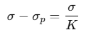
where K is the dielectric constant (relative permittivity) of the material. The capacitance with the dielectric filling the region becomes
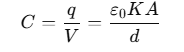
The product ε0K is called the permittivity of the medium and is denoted by ε = ε0K.

For vacuum K = 1 and ε = ε0. The dimensionless ratio

is the dielectric constant of the substance. Thus, inserting a dielectric increases the capacitance by a factor K (>1) compared to the vacuum value.
Special cases:
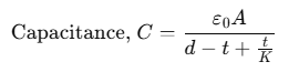
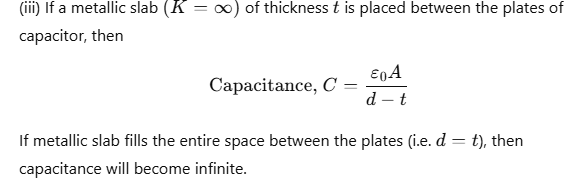
- When a slab of thickness t (t < d) is inserted between the plates, a composite expression for the effective capacitance can be derived treating the arrangement as series combination of two capacitors (one region filled with dielectric, the other vacuum).
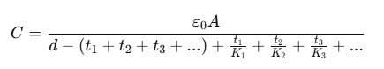
- If several slabs with dielectric constants K1, K2, K3, ... and thicknesses t1, t2, t3, ... are placed in series between the plates, the effective capacitance can be obtained by modelling them as capacitors in series and using the general series formula.
Combination of capacitors
When several capacitors are connected together between two points, we can define an equivalent capacitance Ceq for the combination by the relation Ceq = Q / V, where Q is the total charge stored on the combination for potential difference V.
Two frequently used combinations are:
- Parallel combination
- Series combination
Parallel combination of capacitors
When corresponding plates of capacitors are connected together so that each capacitor has the same potential difference across its plates, the capacitors are in parallel. Each capacitor may store a different charge but the voltage across every capacitor is the same.
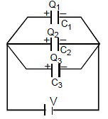
For example, for three capacitors C1, C2, C3 in parallel with common voltage V, the total charge is
Q = Q1 + Q2 + Q3
Using Q = C V for each, we have
Cp V = C1 V + C2 V + C3 V
Therefore the equivalent capacitance of capacitors in parallel is
Ceq = C1 + C2 + C3 + ...
Key points for parallel connection
- All capacitors have the same potential difference across them.
- Equivalent capacitance is the sum of individual capacitances: Ceq = Σ Ci.
- The equivalent capacitance of a parallel arrangement is always greater than the largest individual capacitance in the combination.
- When charging a combination from a battery, energy supplied by the battery is partly stored in the capacitors and (when resistances are present) some energy may be dissipated as heat; in an idealised instant charging with series resistance, half the supplied energy becomes electrostatic energy and half is dissipated as heat during charging.
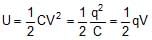
- Energy stored in a capacitor or in a combination can be written as U = 1/2 CV2 = Q2/(2C) = 1/2 QV.


Derivation of formula for parallel combination
For n capacitors in parallel, each has the same voltage V. The total charge stored is the algebraic sum of charges on all capacitors. Using Q = C V for each capacitor and equating to Q = CpV for the combined system leads directly to Cp = Σ Ci.
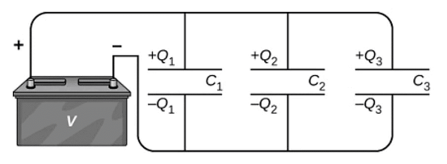
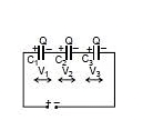
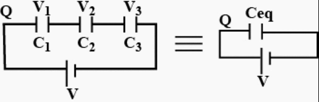
Series combination of capacitors
When capacitors are connected end to end so that the same charge flows through each during charging, they are said to be in series.
In a series combination:
- The charge on each capacitor is the same.
- The total potential difference across the series is the sum of potential differences across the individual capacitors: V = V1 + V2 + V3 + ...
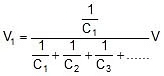
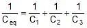
- Since Vi = Q / Ci, we obtain the relation for equivalent capacitance:

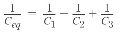
Thus for three capacitors in series:
1 / Ceq = 1 / C1 + 1 / C2 + 1 / C3
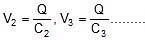

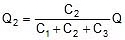
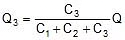
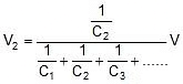
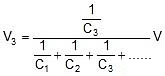
Potential differences across capacitors in series are inversely proportional to their capacitances.

Key points for series connection
- All capacitors in series carry the same magnitude of charge.
- The equivalent capacitance of a series combination is less than the smallest capacitance in the series.
- Energy formulas for combinations follow from U = 1/2 CV2 applied to the equivalent capacitance or to individual capacitors and added.
Equivalent capacitance in series:
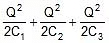
Energy stored in a series combination:

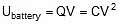
Energy supplied by the battery while charging the series combination is Q × V.


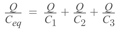
Derivation of formula for series combination
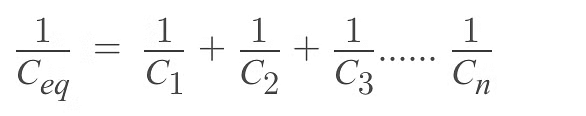
For capacitors C1, C2, C3 in series carrying the same charge Q, write V = V1 + V2 + V3. Use Vi = Q/Ci to obtain Q/Ceq = Q/C1 + Q/C2 + Q/C3, which simplifies to 1/Ceq = Σ 1/Ci. This generalises to any number of capacitors in series.
Examples involving combinations and node-charge methods
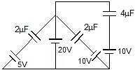
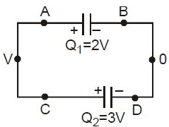
Example 2: Find charge on each capacitor.
Sol:
Charge on C1 = C1 V1 = 2 × (20 - 5) μC
= 30 μC
Charge on C2 = C2 V2 = 2 × (20 - (-10)) μC
= 60 μC
Charge on C3 = C3 V3 = 4 × (20 - 10) μC
= 40 μC
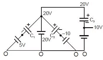
Example 3: Find charge on each capacitor.
Sol:
Write the expression for charge on each capacitor in terms of node potential x:
Charge on C1 = (x - 10) C1
Charge on C2 = (x - 0) C2
Charge on C3 = (x - 20) C3
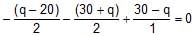
Use charge conservation at node x (sum of charges connected to the node equals zero) to obtain an equation for x:
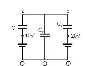
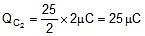
Substituting values and solving gives x = 25 V. From x, compute the individual charges.
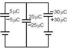
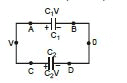
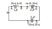
Example 4: In the given circuit find out the charge on each capacitor (initially uncharged).
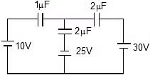
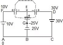
Sol:
Assume potential at A is 0. From circuit find potentials at D, F and G and apply Kirchhoff's node/charge conservation at node E: the total algebraic charge of the plates connected to E must remain equal to its initial value (zero).
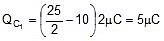
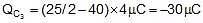
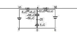
Set up the algebraic equation and solve to obtain x = 4 V as the node potential. Then calculate the charges:
Q2mF = (30 - 4) × 2 = 52 mC
Q1mF = (10 - 4) × 1 = 6 mC
Q2mF = (4 - (-25)) × 2 = 58 mC
Example 5:
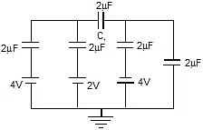
Find voltage across capacitor C1.
Sol:
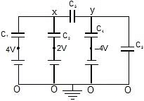
Use charge conservation at nodes x and y to set up two linear equations:
For x:
(x - 4) C1 + (x - 2) C2 + (x - y) C3 = 0
For y:
(y - x) C3 + (y - (-4)) C4 + (y - 0) C5 = 0
Solve the two simultaneous equations to find y = -3 V and x = 7 V. Therefore the potential difference across C1 is x - y, which can be evaluated from the results.


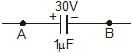
Example 6: Three initially uncharged capacitors are connected in series with a battery of emf 30 V. Find:
- (i) charge flow through the battery,
- (ii) potential energy in the 3 mF capacitor,
- (iii) total energy in capacitors,
- (iv) heat produced in the circuit.
Sol:
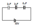
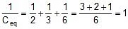
Equivalent capacitance Ceq = 1 μF.
(i) Q = Ceq V = 30 μC.
(ii) Charge on 3 μF capacitor = 30 μC. Energy = 1/2 × C × V2 (or Q2/(2C)). Thus energy for 3 μF capacitor evaluates to 150 μJ.


(iii) Utotal = 450 μJ.

(iv) Heat produced = energy supplied by battery - energy stored = (Q × V) - Utotal = 450 μJ.
Example 7: Two capacitors of capacitance 1 mF and 2 mF are charged to potential differences 20 V and 15 V respectively as shown. If terminals are reconnected as described, find final charges on both capacitors.
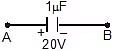
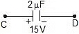
Sol:
Apply Kirchhoff's voltage law or charge conservation to set up the equation for the final charges. Solve the algebraic equation to obtain the change in charge and final values. The worked relation leads to 3q = -10, so charge flow and final charges can be computed from q.
Charge flow = -

μC.
Charge on 1 μF capacitor = 20 + q =

Charge on 2 μF capacitor = 30 + q =

Energy stored in a capacitor
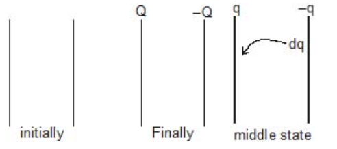
Work must be done to move charge incrementally onto a conductor against the repulsive force of existing charge. This work is stored as electrostatic potential energy in the field.
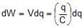
Suppose a capacitor of capacitance C is charged up to potential V0 so that the final charge is q0 = C V0. During charging, when the instantaneous charge is q (< q0), the potential of the conductor is φ = q/C. The infinitesimal work required to bring an increment dq to this potential is dW = (q/C) dq. Integrating from 0 to q0 gives the total work stored as potential energy:

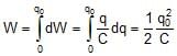
Thus the energy stored is

Using q0 = C V0, the energy can also be written as
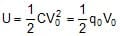
So for a capacitor charged to voltage V and holding charge Q, the energy expressions are
Energy Density of a Charged Capacitor
This energy is localized on the charges or the plates but is distributed in the field. Since in case of a parallel plate capacitor, the electric field is only between the plates, i.e., in a volume (A × d), the energy density
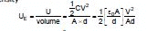
or 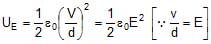
Calculation of Capacitance
The method for the calculation of capacitance involves integration of the electric field between two conductors or the plates which are just equipotential surfaces to obtain the potential difference Vab. Thus,
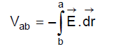
Therefore, 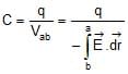
Heat Generated :
(1) Work done by battery
W = QV
Q = charge flow in the battery
V = EMF of battery
(2) W = Ve (When Battery discharging)
W = -Ve (When Battery charging)
(3)  Q = CV (C = equivalent capacitance)
so W = CV × V = CV2
Now energy on the capacitor 
Therefore, Energy dissipated in form of heat (due to resistance)
H = Work done by battery - {final energy of capacitor - initial energy of capacitor}
Change in energy on introducing a dielectric slab
- If a dielectric slab is inserted between the plates while the capacitor remains connected to a battery (voltage held constant), the capacitance increases by factor K and the stored energy becomes K times the initial energy: U → K U0. The extra energy comes from the battery which does work to move charge.
- If a dielectric slab is inserted between plates with the battery disconnected (charge Q held constant), the capacitance increases but the energy stored changes to U' = Q2/(2 C') which is smaller than the initial energy (energy decreases); the difference appears as work done in polarising the dielectric and as heat.

Example 8: When switch S1 is opened and S2 closed, find the heat generated in the circuit.
Sol:
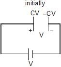
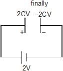
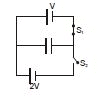
Charge flow through battery = Qf - Qi = 2 C V - C V = C V.
Heat produced H = (charge flow × average potential) - change in stored energy, which evaluates using the given expressions and leads to the final numerical value shown in the worked solution.

Distribution of charges when connecting two charged capacitors
Consider two capacitors C1 and C2 initially charged to Q1, Q2 and potentials V1, V2 respectively. If they are then connected together in some fashion, charges redistribute until common potentials are reached on connected nodes, subject to overall charge conservation. The redistribution generally produces Joule heating in connecting wires.
| Before connecting the capacitors | ||
|---|---|---|
| Parameter | Ist Capacitor | IInd Capacitor |
| Capacitance | C1 | C2 |
| Charge | Q1 | Q2 |
| Potential | V1 | V2 |
| After connecting the capacitors | ||
|---|---|---|
| Parameter | Ist Capacitor | IInd Capacitor |
| Capacitance | C1 | C2 |
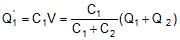
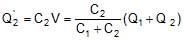
| Charge |  |  |
| Potential | V | V |
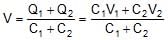
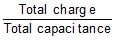
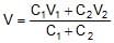
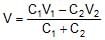
(a) Common potential:
By conservation of total free charge on the connected plates,
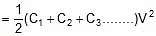
Q1 + Q2 = C1 V + C2 V
(b) Heat loss during redistribution:
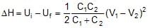
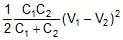
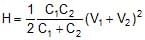
The loss of energy is dissipated as Joule heating in the connecting wire or circuit resistance. The exact expression for the heat loss can be obtained by comparing initial and final stored energies:
- When plates of similar polarity are connected (e.g., + to + and - to -), use positive values for charges and potentials.
- When plates of opposite polarity are connected (+ to -), treat one plate's charge/potential as negative when writing conservation equations.
Derivation of the formulae:
Assume potentials of some reference nodes are zero and let the common potential after connection be V. Using charge conservation and expressions Q = CV before and after connection leads to the formulae for V, final charges and heat H dissipated:
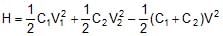
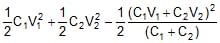
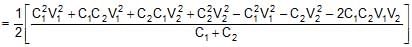
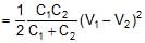
The heat dissipated H equals the initial stored energy minus the final stored energy, yielding
When oppositely charged terminals are connected:
Appropriate sign changes in the conservation equations give the modified expressions:
Worked examples on redistribution of charge and heat
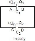
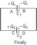
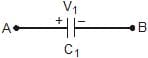
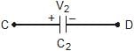
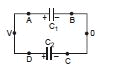
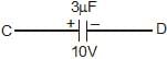
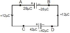
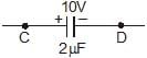
Example 9: If A is connected with C and B is connected with D, find:
- (i) How much charge flows in the circuit.
- (ii) How much heat is produced in the circuit.
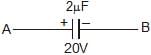
Sol:
(i) Let potential of B and D is zero and common potential on capacitors is V, then at A and C it will be V.
By charge conservation,
3V + 2V = 40 + 30
5V = 70 ⇒ V = 14 volt
Charge flow = 40 - 28 = 12 μC
Now final charges on each plate is shown in the figure.
(ii) Heat produced =  × 2 × (20)2
  × 3 × (10)2 -
  × 5 × (14)2
= 400 150 - 490
= 550- 490 = 60 mJ
- When capacitor plates are joined then the charge remains conserved.
- We can also use direct formula of redistribution as given above.
Example 10: Repeat above question if A is connected with D and B is connected with C.
Sol:
Let potentials of B and C be zero and let the common potential on capacitors be V (so potentials at A and D are V). Then
2V + 3V = 10 ⇒ V = 2 V.
Compute final charges and the heat produced by comparing initial and final stored energies; carrying out the calculation yields H = 540 μJ.
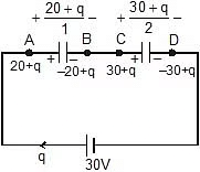
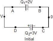
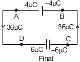
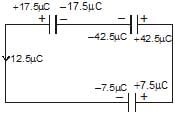
Example 11: Three capacitors as shown of capacitance 1mF, 2mF and 2mF are charged upto potential difference 30 V, 10 V and 15V respectively. If terminal A is connected with D, C is connected with E and F is connected with B. Then find out charge flow in the circuit and find the final charges on capacitors.
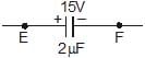
Sol. Let charge flow is q.
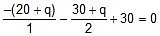
Now applying Kirchhoff's voltage low
- 2q = - 25
q = 12.5 mC
Final charges on plates
Summary (optional)
This chapter covered the definition of capacitance, units, the parallel-plate capacitor and its capacitance C = εA/d, effects of dielectrics including definition of dielectric constant K and permittivity ε = ε0K, combinations of capacitors in series and parallel with their equivalent formulae, energy stored in capacitors and how energy changes when dielectrics are introduced, and redistribution of charge and heat when charged capacitors are connected. Worked examples demonstrate node-charge methods, conservation of charge, energy bookkeeping and use of Kirchhoff's laws to solve typical circuit problems involving capacitors.
FAQs on Capacitors
| 1. What is a parallel plate capacitor and how does it work? |  |
| 2. What are the main applications of capacitors in electronic circuits? | |
| 3. How does a dielectric material affect the capacitance of a parallel plate capacitor? | |
| 4. How do you calculate the equivalent capacitance for capacitors in parallel? | |
| 5. What is the method to find the equivalent capacitance of capacitors in series? | |


