Resistors in Series & Parallel Combinations


Combination of Resistance
Resistors in an electric circuit can be connected in various ways. Any complicated network of resistors can be reduced, for analysis, into combinations of two basic kinds: series and parallel connections. Understanding these two simple combinations and the rules to reduce them is essential for solving more complex networks.
Resistance in Series
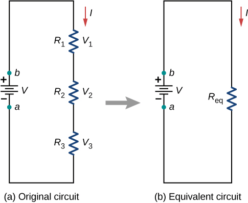
- In a series connection the resistors are joined end to end so that the second end of each resistor is connected to the first end of the next resistor. A source is connected across the first terminal of the first resistor and the last terminal of the last resistor. The figure above shows three resistors R1, R2 and R3 in series. Let the potential differences across these resistors be V1, V2 and V3, respectively.
- The current through each resistor in series is the same and equal to the current supplied by the source.
- Because the current is the same through each resistor but resistances differ, the potential difference across each resistor differs. The applied potential difference is divided among the resistors in the ratio of their resistances (this is the voltage-divider property).
- Ohm's law for each resistor gives:
V1 = I R1,
V2 = I R2,
V3 = I R3. - If the potential difference between the ends of the series string (between points A and D) is V, then
V = V1 + V2 + V3 = I (R1 + R2 + R3). - Replacing the series string by a single equivalent resistor R so that the current for the same applied voltage remains unchanged gives
V = I R = I (R1 + R2 + R3),
therefore
R = R1 + R2 + R3. - Important conclusions for series combination:
(i) The equivalent resistance is greater than the largest individual resistance in the series chain.
(ii) The current supplied by the source equals the current through each resistor.
(iii) The total potential difference is shared among resistors in the ratio of their resistances:
V1 : V2 : V3 = R1 : R2 : R3.
Resistance in Parallel
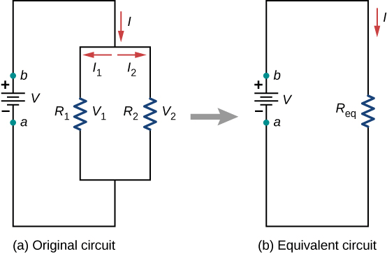
- In a parallel connection two or more resistors are connected so that their corresponding terminals are joined: all first terminals are connected together to one node and all second terminals to another node. The figure above shows three resistors R1, R2 and R3 connected in parallel between points A and B. Let the total current from the source be I; at junction A this current divides into i1, i2 and i3 through R1, R2 and R3, respectively.
- Because each resistor is connected across the same two points A and B, the potential difference across each resistor is the same and equals the applied potential difference V.
- By Ohm's law, the currents through individual resistors are:
i1 = V / R1,
i2 = V / R2,
i3 = V / R3. - The total current leaving the source is the sum of branch currents:
I = i1 + i2 + i3 = V (1/R1 + 1/R2 + 1/R3). - If the parallel network is replaced by a single equivalent resistor R between A and B, then
I = V / R = V (1/R1 + 1/R2 + 1/R3),
so
1/R = 1/R1 + 1/R2 + 1/R3. - Important conclusions for parallel combination:
(i) The equivalent resistance is smaller than the smallest individual resistance in the parallel group.
(ii) The applied potential difference across the combination equals the potential difference across each resistor.
(iii) The current supplied by the source equals the algebraic sum of branch currents; the currents divide inversely in the ratio of resistances:
i1 : i2 : i3 = 1/R1 : 1/R2 : 1/R3 = R2R3 : R1R3 : R1R2 (for pairwise comparison). - For two resistors in parallel, a commonly used formula is:
1/R = 1/R1 + 1/R2,
or equivalently
R = (R1 R2) / (R1 + R2). - Power dissipated in a resistor can be written as:
P = I²R = V² / R = VI.
In a parallel circuit where V is the same across all branches, a smaller resistance dissipates more power (P ∝ 1/R for fixed V). Thus, a low resistance branch draws a larger current and can produce larger heating.
Note:
(i) If two or more resistances are joined in parallel then iR = i1R1 = i2R2 = i3R3 ...
That is, iR = constant; a low resistance joined in parallel always draws a higher current.
(ii) When two resistances R1 and R2 are joined in parallel, then
That is, heat produced will be maximum in the lowest resistance (when V is the same across each resistor).


Worked Examples
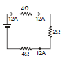
Example 1. Find current which is passing through battery.
Sol.
Identify the resistors that are clearly in series or parallel by inspection of the circuit diagram.
Combine series resistors by adding their resistances.
Combine parallel resistors using 1/R = Σ(1/Ri).
Repeat this process until the entire network between the battery terminals is reduced to a single equivalent resistance Req.
Compute the current delivered by the battery using Ohm's law for the complete circuit:
Vbattery divided by total resistance of the circuit (including any internal resistance of the battery, if present):
I = Vbattery / (Req + rinternal).
Refer to the diagram above for the specific connections; the algebraic reduction steps are shown in the image.

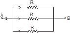
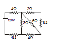
Example 2. Find equivalent resistance.
Sol.
Examine which resistors are directly across the same two nodes (parallel) and which are end-to-end (series).
Replace simple series or parallel groups step by step with their equivalent resistances until only one resistor remains between terminals A and B; that value is Req.
All resistors are connected between terminals A and B; the intermediate simplification is shown in the modified circuit image.
Therefore, Req = the expression shown in the figure.

Example 3. Find the current in resistance P if voltage supply between A and B is V volts.
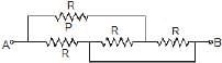
Sol.
Reduce the network to find the total equivalent resistance Req between A and B.

Compute the total current from the source:
I = V / Req.
Redraw the modified circuit after reduction to identify the branch containing resistor P and how the total current divides.
Use the current-division or voltage-division relations, as appropriate, to find the current through P. The intermediate steps and the modified circuit are shown in the images.

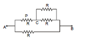
The branch current through P is given by the expression shown in the figure.


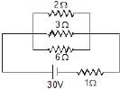
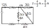
Example 4. Find the current in 2 Ω resistance.
Sol.
Combine the obvious series and parallel groups stepwise and record each reduction on a new line.
2 Ω and 1 Ω in series combine to give 3 Ω.
3 Ω in parallel with 6 Ω combine using 1/R = 1/3 + 1/6 to give their equivalent; the resulting value is shown in the image.
Combine other series groups similarly: 2 Ω and 4 Ω in series give 6 Ω.
Combine 6 Ω and the previously found equivalent in parallel; the result is shown in the image.
The final equivalent resistance of the whole network is Req = 10 Ω (as obtained by the reductions shown).

Compute the total current supplied by the battery (shown in the diagram) using I_total = V / Req.
The current through the 2 Ω resistor is then found by following the reduced circuit and applying appropriate division rule; the algebraic expression and the numeric value appear in the figure.


Special Problems: Identical Potentials and Symmetry
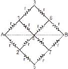
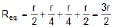
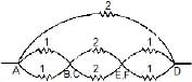
- In some networks certain nodes are at the same potential due to symmetry or direct shorting. Identifying these nodes greatly simplifies the reduction. The figure above shows such a case: points (1, 2), (3, 4, 5) and (6, 7) are at the same potential. The circuit can therefore be redrawn with those points merged to simplify the network.
- Once nodes of equal potential are identified, some resistors become clearly in series or parallel and can be reduced accordingly.
- The equivalent resistance of a series chain is the sum of resistances. Use the simple replacement step shown in the image to reduce the chain.

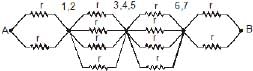
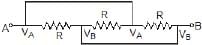
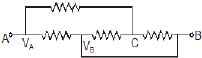
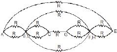
In the next figure the resistances (in ohms) are arranged with certain points at equal potential (B and C; E and F). The circuit can be redrawn to exploit these equal potentials and then reduced to find the equivalent resistance between A and D. The reduction steps and final simplification are shown in the images.
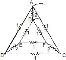
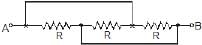
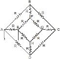
In the final example shown, all resistances are equal (value R). By identifying pairs of nodes at the same potential (B and D have same potential; F and H have same potential) the network reduces to a simpler equivalent circuit. The reduction yields the overall equivalent resistance between A and E as 7R/2. The stepwise re-drawing and simplification are shown in the images.

Methods and Strategies for Solving Resistance Networks
- Look for simple series or parallel groups first; replace them by their equivalent resistance and repeat.
- Use symmetry: if two nodes are at the same potential, the resistor(s) between them carry no current and can be removed (or nodes may be merged) to simplify the circuit.
- For bridges that are not simple series/parallel (e.g., Wheatstone bridge), check if the bridge is balanced. If balanced, the bridge resistor carries no current and can be ignored in that reduction step.
- If series/parallel reduction is not possible directly, use Kirchhoff's laws or node-voltage/mesh-current methods to obtain currents or potentials, then compute equivalent resistance if required.
- Keep track of units and redraw the circuit after each reduction to avoid confusion.
Summary
Resistors in series add directly; resistors in parallel add as reciprocals. In series the same current flows through every resistor and voltages divide in proportion to resistance. In parallel the same voltage appears across every branch and currents divide inversely with resistance. Use stepwise reduction, symmetry, and circuit laws to handle more complex networks. Apply power formulas appropriately when calculating dissipation in resistors.
FAQs on Resistors in Series & Parallel Combinations
| 1. What is the formula to calculate the total resistance of resistors in series? |  |
| 2. How do you calculate the total resistance of resistors in parallel? | |
| 3. What is the difference between series and parallel circuits? | |
| 4. Can resistors be connected in both series and parallel in the same circuit? | |
| 5. How do you calculate the total resistance of a combination circuit? | |


