Electromagnetic Induction: Part 2 | Physics Class 12 - NEET PDF Download
What is Inductance?
- Inductance is like a resistance to changes in electric current in a wire. We measure it in Henrys, where 1 Henry means it takes 1 volt to make a change in current of 1 Ampere per second.
- When electricity moves through a wire, it makes a magnetic field. If the current changes, this field changes too, which creates a kind of electric push-back. This push-back is what we call inductance. We use a component called an inductor to add inductance to a circuit.
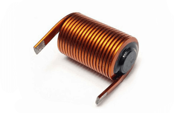 An Inductor
- Inductance is classified into two types as:
- Self Inductance
- Mutual Inductance
Self induction
- Self induction is induction of emf in a coil due to its own current change. Total flux N
 passing through a coil due to its own current is proportional to the current and is given as N
  = L i where L is called coefficient of self induction or inductance.
 - The inductance L is purely a geometrical property i.e., we can tell the inductance value even if a coil is not connected in a circuit. Inductance depends on the shape and size of the loop and the number of turns it has.
If current in the coil changes by ΔI in a time interval Δt, the average emf induced in the coil is given as
ε =  =
= 
The instantaneous emf is given as
ε = - = -
= - 
S.I unit of inductance is wb/amp or Henry (H)
L - self inductance is +ve Quantity.
L depends on :
(1) Geometry of loop
(2) Medium in which it is kept.
L does not depend upon current. L is a scalar Quantity.
Self Inductance of solenoid
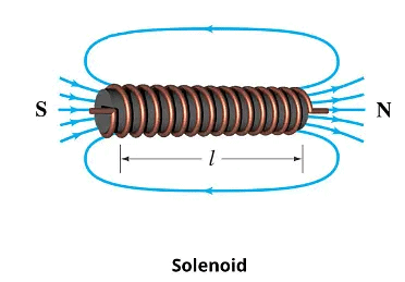 Let the volume of the solenoid be V, the number of turns per unit length be n. Let a current I be flowing in the solenoid. Magnetic field in the solenoid is given as B = μ0 nl. The magnetic flux through one turn of solenoid f = μ0 n l A.
The total magnetic flux through the solenoid = N 
= N μ0 n l A
= μ0 n2 l A l
Therefore, L = μ0 n2 l A = μ0 n2 V
Ф= μ0 n i pr2 (n l)
L = Ф/i = μ0 n2 πr2 l
Inductance per unit volume = μ0 n2
Ex. The current in a coil of self-inductance L = 2H is increasing according to the law i = 2 sin t2. Find the amount of energy spent during the period when the current changes from 0 to 2 ampere.
Sol. Let the current be 2 amp at t = τ
Then 2 = 2 sin τ2 ⇒ τ = 
When the instantaneous current is i, the self induced emf is L  . If the amount of charge that is displaced in time dt is dθ, then the elementary work done
= 
W =  =
= 
W =  =
= 
Let θ = 2t2
Differentiating dθ = 4t dt
Therefore, W = 
= L (- cosθ) = - L cos 2t2
W = 
= 2 L = 2 × 2 = 4 joule
Inductor
It is represented by

electrical equivalence of loop
 ⇒
⇒ 

If current i through the inductor is increasing the induced emf will oppose the increase in current and hence will be opposite to the current. If current i through the inductor is decreasing the induced emf will oppose the decrease in current and hence will be in the direction of the current.

Over all result

VA - L  = VB
= VB
Note
 If there is a resistance in the inductor (resistance of the coil of inductor) then :


Ex. A B is a part of circuit. Find the potential difference vA - vB if

(i) current i = 2A and is constant
(ii) current i = 2A and is increasing at the rate of 1 amp/sec.
(iii) current i = 2A and is decreasing at the rate 1 amp/sec.
Sol. 
 =
= 
writing KVL from A to B
VA - 1 - 5 - 2 i = VB
(i) Put i = 2,  = 0
= 0
VA - 5 - 4 = VB Therefore, VA - VB = 9 volt
(ii) Put i = 2,  = 1 ;
= 1 ;
VA - 1 - 5 - 4 = VB or VA - VB = 10 V0
(iii) Put i = 2,  = - 1
= - 1
VA + 1 - 5 - 2 × 2 = VB
VA = 8 volt
Ex. Find current i, i1 and i2 in the following circuit.

Sol. at t = 0
i = i2 =  and i1 = 0
at t = ∞

⇒ i1 = i2 =  =
= 
Energy stored in an inductor
If current in an inductor at an instant is i and is increasing at the rate di/dt, the induced emf will oppose the current. Its behaviour is shown in the figure.

Power consumed by the inductor = i L 
Energy consumed in dt time = i L  dt
dt
Therefore, total energy consumed as the current increases from 0 to I = 
=  ⇒ U =
⇒ U = 
Note :
 This energy is stored in the magnetic field with energy density

Total energy U = 
Ex. Find out the energy per unit length ratio inside the solid long wire having current density J.

Sol. Take a ring of radius r and thickness dr as an element inside the wire
 =
= 
using B = 

 ⇒
⇒  ⇒
⇒ 
Mutual Inductance
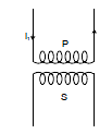
- Consider two coils P and S placed close to each other as shown in the figure. When the current passing through a coil increases or decreases, the magnetic flux linked with the other coil also changes and an induced e.m.f. is developed in it.
- This phenomenon is known as mutual induction. This coil in which current is passed is known as primary and the other in which e.m.f. is developed is called as secondary.
Let the current through the primary coil at any instant be i1. Then the magnetic flux  in the secondary at any time will be proportional to i1 i.e.,
  is directly proportional to i1
Therefore the induced e.m.f. in secondary
when i1 changes is given by
 i.e.,
i.e., 
 =
=  ⇒
⇒  = M i1
where M is the constant of proportionality and is known as mutual inductance of two coils. It is defined as the e.m.f. induced in the secondary coil by unit rate of change of current in the primary coil. The unit of mutual inductance is henry (H).
Mutual Inductance of a Pair of Solenoids one Surrounding the other coil
Figure shows a coil of N2 turns and radius R2 surrounding a long solenoid of length l1, radius R1 and number of turns N1.
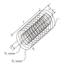
To calculate mutual inductance M between them, let us assume a current i1 through the inner solenoid S1
There is no magnetic field outside the solenoid and the field inside has magnitude,

and is directed parallel to the solenoid's axis. The magnetic flux  through the surrounding coil is, therefore,

Now, 
Notice that M is independent of the radius R2 of the surrounding coil. This is because solenoid's magnetic field is confined to its interior.
Ex.Find the mutual inductance of two concentric coils of radii a1 and a2 (a1 << a2) if the planes of coils are same.

Sol. Let a current i flow in coil of radius a2.
Magnetic field at the centre of coil =
or M i =  or
or 
Ex. Solve the above question, if the planes of coil are perpendicular.
Sol. Let a current i flow in the coil of radius a1. The magnetic field at the centre of this coil will now be parallel to the plane of smaller coil and hence no flux will pass through it, hence M = 0
Ex. Solve the above problem if the planes of coils make θ angle with each other.
Sol. If i current flows in the larger coil, the magnetic field produced at the centre will be perpendicular to the plane of larger coil.
Now the area vector of smaller coil which is perpendicular to the plane of smaller coil will make an angle θ with the magnetic field.
Thus flux =  . πa12 cos θ
or M = 
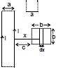
Ex. Find the mutual inductance between two rectangular loops, shown in figure.

Sol. Let current i flow in the loop having ∞-by long sides. Consider a segment of width dx at a distance x as shown flux through the regent
d =
= 
⇒  =
= 
= 
Ex. Figure shows two concentric coplanar coils with radii a and b (a << b). A current i = 2t flows in the smaller loop. Neglecting self inductance of larger loop

(a) Find the mutual inductance of the two coils
(b) Find the emf induced in the larger coil
(c) If the resistance of the larger loop is R find the current in it as a function of time
Sol. (a) To find mutual inductance, it does not matter in which coil we consider current and in which flux is calculated (Reciprocity theorem) Let current i be flowing in the larger coil. Magnetic field at the centre =  .
.
flux through the smaller coil = 
Therefore, M = 
(ii) |emf induced in larger coil| = 
=  =
= 
(iii) current in the larger coil = 
Ex. If the current in the inner loop changes according to i = 2t2 then, find the current in the capacitor as a function of time.

Sol. M = 
|emf induced in larger coil| = 
e =  =
= 

Applying KVL : -
+e -  - iR = 0 ⇒
  - -iR = 0
differentiate wrt time :  -
-  -
-  on solving it i =
Series Combination of Inductors
 =
= 
Therefore, V = V1 + V2

Leθ = L1 + L2 +.................
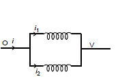
Parallel Combination of inductor
i = i1 + i2 ⇒ 


What are Eddy Currents?
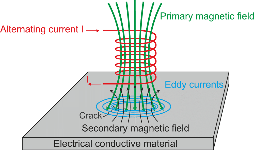
- An eddy current is a current set up in a conductor in response to a changing magnetic field. They flow in closed loops in a plane perpendicular to the magnetic field. By Lenz law, the current swirls in such a way as to create a magnetic field opposing the change; for this to occur in a conductor, electrons swirl in a plane perpendicular to the magnetic field.
- Because of the tendency of eddy currents to oppose, eddy currents cause a loss of energy. Eddy currents transform more useful forms of energy, such as kinetic energy, into heat, which isn’t generally useful.
 Formation of Eddy Currents
Some Practical Applications
In the Brakes of Trains
During braking, the brakes expose the metal wheels to a magnetic field which generates eddy currents in the wheels. The magnetic interaction between the applied field and the eddy currents acts to slow the wheels down. The faster the wheels spin, the stronger is the effect, meaning that as the train slows the braking force is reduces, producing a smooth stopping motion.
Electromagnetic damping
- Used to design deadbeat galvanometers. Usually, the needle oscillates a little about its equilibrium position before it comes to rest. This causes a delay in taking the reading so to avoid this delay, the coil is wound over a non-magnetic metallic frame.
- As the coil is deflected, eddy currents set up in the metallic frame and thus, the needle comes to rest almost instantly.
- Thus, the motion of the “coil is damped”. Certain galvanometers have a fixed core made up of nonmagnetic metallic material. When the coil oscillates, the eddy currents that generate in the core oppose the motion and bring the coil to rest.
Electric Power Meters
The shiny metal disc in the electric power meter rotates due to eddy currents. The magnetic field induces the electric currents in the disc. You can also observe the shiny disc at your house.
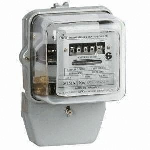 Electric power meters
Induction Furnace
In a rapidly changing magnetic fields, due to a large emf produced, large eddy currents are set up. Eddy currents produce temperature. Thus a large temperature is created. So a coil is wound over a constituent metal which is placed in a field of the highly oscillating magnetic field produced by high frequency. 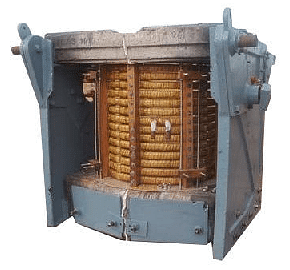 Industrial induction furnace
The temperature produced is enough to melt the metal. This is used to extract metals from ores. Induction furnace can be used to prepare alloys, by melting the metals at a very high temperature.
Speedometers
To know the speed of any vehicle, these currents are used. A speedometer consists of a magnet which keeps rotating according to the speed of our vehicle. Eddy currents are been produced in the drum. As the drum turns in the direction of the rotating magnet, the pointer attached to the drum indicates the speed of the vehicle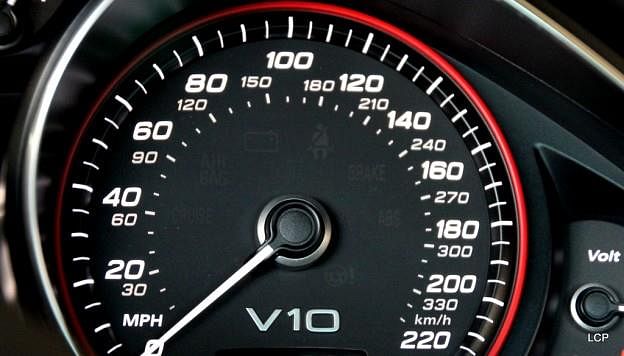 SpeedometerQues: Eddy currents are produced in a metallic conductor when
(a) The magnetic flux linked with it changes
(b) It is placed in the changing magnetic field
(c) Placed in the magnetic field
(d) Both A and B
Ans: D
Solution: They are produced when the magnetic flux passing through the metal object continuously changes. This may happen due to many reasons.
1. The object is placed in the region with changing magnetic field.
2. The object continuously moves in and out of the magnetic field region.
Power dissipation of eddy currents
Under certain assumptions (uniform material, uniform magnetic field, no skin effect, etc.) the power lost due to eddy currents per unit mass for a thin sheet or wire can be calculated from the following equation:
 where
where
P is the power lost per unit mass (W/kg),
Bp is the peak magnetic field (T),
d is the thickness of the sheet or diameter of the wire (m),
f is the frequency (Hz),
k is a constant equal to 1 for a thin sheet and 2 for a thin wire,
ρ is the resistivity of the material (Ω m), and
D is the density of the material (kg/m3).
This equation is valid only under the so-called quasi-static conditions, where the frequency of magnetisation doe snot result in the skin effect; that is, the electromagnetic wave fully penetrates the material.
Diffusion Equation
The derivation of a useful equation for modelling the effect of eddy currents in a material starts with the differential, magnetostatic form of Ampère’s Law, providing an expression for the magnetizing field H surrounding a current density J:

Taking the curl on both sides of this equation and then using a common vector calculus identity for the curl of the curl results in

From Gauss’s law for magnetism, ∇ ·H = 0, so

Using Ohm’s law, J = σE, which relates current density J to electric field E in terms of a material’s conductivityσ,and assuming isotropic homogeneous conductivity, the equation can be written as

Using the differential form of Faraday’s law, ∇ × E = −∂B/∂t, this gives

By definition, B = μ0(H+M), where M is the magnetization of the material and μ0 is the vacuum permeability. The diffusion equation therefore is

AC Generator
An AC generator is an electric generator that converts mechanical energy into electrical energy in form of alternative emf or alternating current. AC generator works on the principle of ”Electromagnetic Induction”.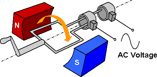
Parts of an AC Generator
An Ac generator consists of two poles i.e is the north pole and south pole of a magnet so that we can have a uniform magnetic field. There is also a coil which is rectangular in shape that is the armature. These coils are connected to the slip rings and attached to them are carbon brushes.
The slip rings are made of metal and are insulated from each other. The brushes are carbon brushes and one end of each brush connects to the ring and other connects to the circuit. The rectangular coils rotate about an axis which is perpendicular to the magnetic field. There is also a shaft which rotates rapidly.
Working of an AC Generator
When the armature rotates between the poles of the magnet upon an axis perpendicular to the magnetic field, the flux which links with the armature changes continuously. Due to this, an emf is induced in the armature. This produces an electric current through the galvanometer and the slip rings and brushes.
The galvanometer swings between the positive and negative values. This indicates that there is an alternating current flowing through the galvanometer.
Emf induced in an AC generator
If the coil of N turn and area A is rotated at v revolutions per second in a uniform magnetic field B, then the motional emf produced is e = NBA(2πv)sin(2πv)t, where we assume that at time t = 0 s, the coil is perpendicular to the field. The direction of the induced emf is given by Fleming’s right-hand rule or the Lenz’s law.
Fleming’s right-hand rule states that, stretch the forefinger, the middle finger and the thumb of the right hand such that they are manually perpendicular to each other. If the forefinger indicates the direction of the magnetic field, rhumb indicates the direction of the motion of the conductor. The middle finger indicates the direction of the induced current in the conductor.
3-Phase AC generator
In a symmetric three-phase power supply system, three conductors each carry an alternating current of the same frequency and voltage amplitude relative to a common reference but with a phase difference of one third the period. The common reference usually connects to ground and often to a current-carrying conductor that is neutral.
Due to the phase difference, the voltage on any conductor reaches its peak at one-third of a cycle after one of the other conductors and one-third of a cycle before the remaining conductor. This phase delay gives constant power transfer to a balanced linear load. It also makes it possible to produce a rotating magnetic field in an electric motor and generate other phase arrangements using transformers.
Solve Questions
Q.1. What replacement is required to convert an AC generator to DC generator
(a) Armature with coil
(b) Concave magnets with horseshoe magnet
(c) Slip rings with split rings
(d) All of the above
Ans: (c)
Solution: The slip rings in an AC generator maintain a connection between a moving rotor and the stationary rotor results in the periodic change of current in the loop making it an alternate current. However, the DC generator is consisting of split rings makes the current change direction every half rotation which causes no change in direction of the current.
Q.2. What determines the frequency of a.c. produced by a generator?
(a) The number of rotations of coil in one-second
(b) A speed of rotation coil
(c) Both A and B
(d) None of the above
Ans: (c)
Solution: A frequency of ac, v= w/2π, where w is the speed of rotation.
|
97 videos|336 docs|104 tests
|
FAQs on Electromagnetic Induction: Part 2 - Physics Class 12 - NEET
| 1. What is inductance and how is it measured? |  |
| 2. What is self-induction and how does it occur in a solenoid? |  |
| 3. How is the self-inductance of a solenoid calculated? |  |
| 4. What are eddy currents and what are their effects in electrical applications? |  |
| 5. How do inductors behave in series and parallel combinations? |  |

|
Explore Courses for NEET exam
|

|
 passing through a coil due to its own current is proportional to the current and is given as N
  = L i where L is called coefficient of self induction or inductance.