Alternating Current Chapter Notes | Physics Class 12 - NEET PDF Download
| Table of contents |
|
| Alternating Current |
|
| Average and RMS value of Alternating Current |
|
| Power in an AC circuit |
|
| Series AC Circuit |
|
| Series L-R Circuit |
|
| Series C-R Circuit |
|
| L.C. Circuit |
|
| Series L-C-R Circuit |
|

Alternating Current
Until now, we have studied only circuits with direct current (dc) which flows only in one direction. The primary source of emf in such circuit is a battery. When a resistance is connected across the terminals of the battery, a current is established in the circuits, which flows in a unique direction from the positive terminal to the negative terminal via the external resistance.
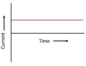 Direct current
 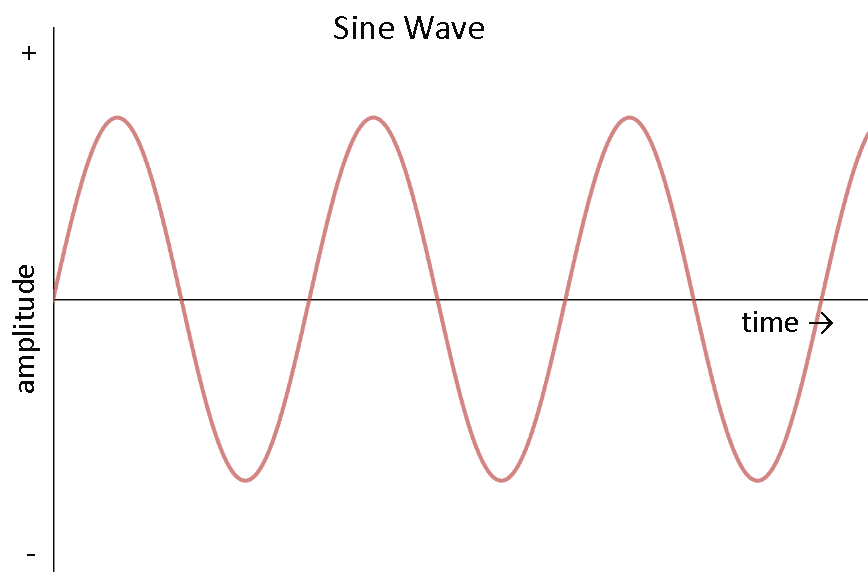 Alternating current
But most of the electric power generated and used in the world is in the form of alternating current (ac), the magnitude of which changes continuously with time and direction is reversed periodically (as shown in figure III & IV) and it is given by
i = i0 sin (ωt + φ)
Here i is instantaneous value of current i.e., the magnitude of current at any instant of time and i0 is the maximum value of current which is called peak current or the current amplitude and the current repeats its value after each time interval T =  as shown in figure. This time interval is called the time period and w is angular frequency which is equal to 2π times of frequency f.
ω = 2πf
 AC wave
 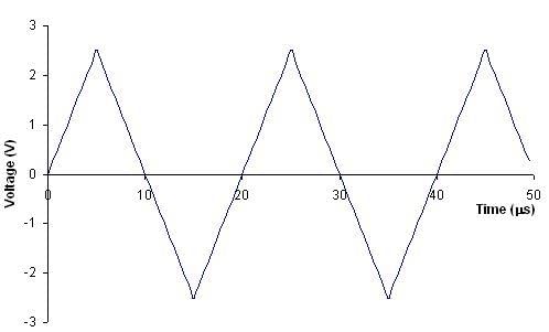 Triangular wave
The current is positive for half the time period and negative for remaining half period. It means that the direction of current is reversed after each half time period. The frequency of ac in India is 50 Hz.
An alternating voltage is given by:
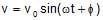
V = V0 sin (ωt + φ)
It also varies alternatively as shown in the figure (b), where V is instantaneous voltage and V0 is peak voltage. It is produced by ac generator also called as ac dynamo.
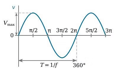 AC Voltage
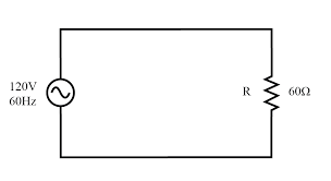
AC Circuit: An ac circuit consists of circuit element i.e., resistor, capacitor, inductor or any combination of these and a generator that provides the alternating current as shown in figure. The ac source is represented by symbol  in the circuit.
 AC Circuit
Average and RMS value of Alternating Current
Average current (Mean current)
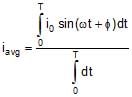
As we know an alternating current is given by
i = i0 sin (ωt + f) ...(1)
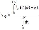
The mean or the average value of ac over any time T is given by

Using equation (1)
In one complete cycle, the average current
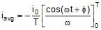 = -
= -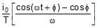 =
= 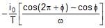 = 0 (as ωT = 2π)
Since ac is positive during the first half cycle and negative during the other half cycle so iavg will be zero for long time also. Hence the dc instrument will indicate zero deflection when connected to a branch carrying ac current. So it is defined for either positive half cycle or negative half cycle.
 =
= 
 0.637 i0
Similarly Vavg = 
 0.637 V0
Ex. 1 If a direct current of value a ampere is superimposed on an alternating current i = b sin wt flowing through a wire, what is the effective value of the resulting current in the circuit ?
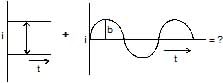
Ans: As current at any instant in the circuit will be,
i = idc + iac = a + b sin ωt
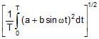
So, ieff = 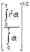 =
= 
i.e., = 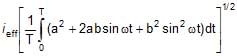
but as
 = 0 and
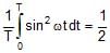
So, ieff = 
R.M.S Value of alternating current
The notation rms refers to root mean square, which is given by square root of mean of square current.
i.e., 
i2avg = 
=  =
= 
=  =
=
 =
= 
irms =  » 0.707 i0
Similarly the rms voltage is given by
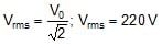
Vrms =  » 0.707 V0
The significance of rms current and rms voltage may be shown by considering a resistance R carrying a current i = i0 sin (wt + f)
The voltage across the resistor will be
VR = Ri = (i0R) sin (ωt + φ)
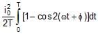
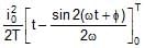
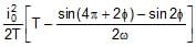
The thermal energy developed in the resistor during the time t to t + dt is
i2 R dt = i02R sin2(ωt + φ) dt
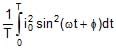
The thermal energy developed in one time period is
U =  =
= 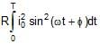 = RT
= RT 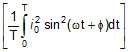 = i2rms RT
It means the root mean square value of ac is that value of steady current, which would generated the same amount of heat in a given resistance in a given time.
So in ac circuits, current and ac voltage are measured in terms of their rms values. Likes when we say that the house hold supply is 220 V ac it means the rms value is 220 V and peak value is = 311 V.
Ex. 2 If the voltage in an ac circuit is represented by the equation, V = sin (314t - φ),calculate (a) peak and rms value of the voltage, (b) average voltage, (c) frequency of ac.
Ans: (a) For ac voltage,
V = V0 sin (ωt - φ)
The peak value of voltage
V0 =  = 311 V
The rms value of voltage
(b) Average voltage in full cycle is zero. Average voltage in half cycle is
Vavg =  =
=  = 198.17 V
(c) As ω = 2πf, 2ωf = 314
i.e., f =  = 50 Hz
Ex. 3 The electric current in a circuit is given by i = i0 (t/T) for some time. Calculate the rms current for the period t = 0 to t = T.
Ans: The mean square current is
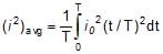 =
= 
Thus, the rms current is
irms = 
Power in an AC circuit
In case of a steady current the rate of doing work is given by,
P = Vi
In an alternating circuit, current and voltage both vary with time, so the work done by the source in time interval dt is given by
dW= Vidt
Suppose in an ac, the current is leading the voltage by an angle φ. Then we can write,
V = V0 sinωt
and i = i0 sin(ωt + φ)
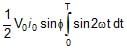
dW = V0i0 sin ωt sin (ωt + φ) dt
= V0 i0 (sin2 ωt cos f + sinωt cos ωt sin φ) dt
The total work done in a complete cycle is
W = V0i0 cos
 + V0i0sin
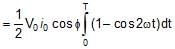 +
+  =
= 
The average power delivered by the source is, therefore,
P =  =
=  =
= 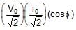
= Vrms irms cos φ
or Pone cycle = Vrms irms cos φ
- Here, the term cos φ is known as the power factor.
- It is said to be leading if current leads voltage, lagging if current lags voltage. Thus, a power factor of 0.5 lagging means current lags the voltage by 60° (as cos-10.5 = 60°). The product of Vrms and irms gives the apparent power. While the true power is obtained by multiplying the apparent power by the power factor cos φ. Thus,
- and apparent power = Vrms × irms
- True power = apparent power × power factor
- For φ= 0°, the current and voltage are in phase. The power is thus, maximum (Vrms× irms). For
- φ = 90°, the power is zero. The current is then stated as wattless. Such a case will arise when resistance in the circuit is zero. The circuit is purely inductive or capacitive.
Series AC Circuit
- When only Resistance is in an AC circuit
Consider a simple ac circuit consisting of a resistor of resistance R and an ac generator, as shown in the figure. According to Kirchhoff's loop law at any instant, the algebraic sum of the potential difference around a closed loop in a circuit must be zero.

ε - VR = 0
ε - iRR = 0
ε0 sinωt - iRR = 0
iR =  sinωt = i0 sin ωt ..(i)
where i0 is the maximum current. i0 = 
From above equations, we see that the instantaneous voltage drop across the resistor
VR = i0R sinωt ...(ii)
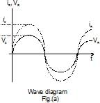
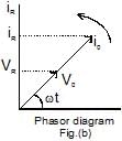
We see in equation (i) & (ii), iR and VR both vary as sin wt and reach their maximum values at the same time as shown in figure (a), they are said to be in phase. A phasor diagram is used to represent phase relationships. The lengths of the arrows correspond to V0 and i0. The projections of the arrows onto the vertical axis give VR and iR. In case of the single-loop resistive circuit, the current and voltage phasors lie along the same line, as shown in figure (b), because iR and VR are in phase.
- When only Inductor is in An AC circuit
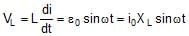
Now consider an ac circuit consisting only of an Inductor of inductance L connected to the terminals of an ac generator, as shown in the figure. The induced emf across the inductor is given by Ldi/dt. On applying Kirchhoff's loop rule to the circuit
ε- VL = 0 ⇒ ε - L
When we rearrange this equation and substitute
ε = ε0 sin ωt, we get 
 = ε0 sin ωt ...(iii)
Integration of this expression gives the current as a function of time
iL =  = -
= - 
For average value of current over one time period to be zero, C = 0
Therefore, iL = - 
When we use the trigonometric identity
coswt = - sin(wt - p/2), we can express equation as
iL =  ...(iv)
From equation (iv), we see that the current reaches its maximum values when cos wt = 1.
i0 =  =
=  ...(v)
where the quantity XL, called the inductive reactance, is
XL = ωL
The expression for the rms current is similar to equation (v), with ε0 replaced by εrms.
Inductive reactance, like resistance, has unit of ohm.
We can think of equation (v) as Ohm's law for an inductive circuit.
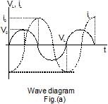
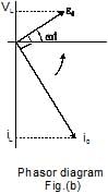
On comparing result of equation (iv) with equation (iii), we can see that the current and voltage are out of phase with each other by π/2 rad, or 90º. A plot of voltage and current versus time is given in figure (a). The voltage reaches its maximum value one quarter of an oscillation period before the current reaches its maximum value. The corresponding phasor diagram for this circuit is shown in figure (b). Thus, we see that for a sinusoidal applied voltage, the current in an inductor always lags behind the voltage across the inductor by 90º.
Ex.4 An inductor of inductance L = 5 H is connected to an
AC source having voltage v = 10 sin (10t +  )
)
Find 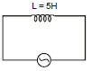
(i) Inductive Reactance (xL)
(ii) Peak & Rms voltage (V0 & Vrms)
(iii) Peak & Rms current (I0 & Irms)
(iv) Instantaneous current (I(t))
Sol. (i) xL = ωL = 10 × 5 = 50
(ii) v0 = 10
vrms = 
(iii) 
Irms = 
(iv) I(t) = 
- When only Capacitor is in An AC circuit
Figure shows an ac circuit consisting of a capacitor of capacitance C connected across the terminals of an ac generator. On applying Kirchhoff's loop rule to this circuit, we get
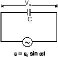
ε - VC = 0
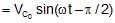
VC = ε = ε0 sin ωt ...(vi)
where VC is the instantaneous voltage drop across the capacitor. From the definition of capacitance, VC = Q/C, and this value for VC substituted into equation gives
Q = C ε0 sin ωt
Since i = dQ/dt, on differentiating above equation gives the instantaneous current in the circuit.
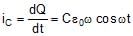
Here again we see that the current is not in phase with the voltage drop across the capacitor, given by equation (vi). Using the trigonometric identity cos ωt = sin(ωt + π/2), we can express this equation in the alternative from
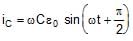 ...(vii)
From equation (vii), we see that the current in the circuit reaches its maximum value when cos ωt= 1.

Where XC is called the capacitive reactance.

The SI unit of XC is also ohm. The rms current is given by an expression similar to equation with V0 replaced by Vrms.
Combining equation (vi) & (vii), we can express the instantaneous voltage drop across the capacitor as
VC = V0 sin ωt = i0 XC sin ωt
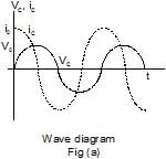
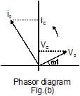
Comparing the result of equation (v) with equation (vi), we see that the current is π/2 rad = 90º out of phase with the voltage across the capacitor. A plot of current and voltage versus time, shows that the current reaches its maximum value one quarter of a cycle sooner than the voltage reaches its maximum value. The corresponding phasor diagram is shown in the figure (b). Thus we see that for a sinusoidally applied emf, the current always leads the voltage across a capacitor by 90º.
Brain Teaser
What is the reactance of a capacitor connected to a constant DC source ?
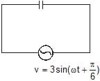
Ex.5 A capacitor of capacitive reactance 5? is connected with A.C. source having voltage V = 3 sin (ωt + p/6). Find rms and Peak voltage rms and peak current and instantaneous current
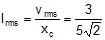
Sol. On comparing with
 ⇒ v0 = 3
 ⇒
⇒ 
 ⇒ I(t) = I0 sin
Series L-R Circuit
- Now consider an ac circuit consisting of a resistor of resistance R and an inductor of inductance L in series with an ac source generator.
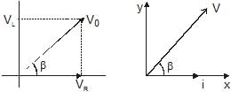
- Suppose in phasor diagram, current is taken along positive x-direction. The VR is also along positive x-direction and VL along positive y-direction as we know that potential difference across a resistance in ac is in phase with current and it leads in phase by 90º with current across the inductor, and as we know VR = i0R & V0 = i0XL
i = i0 sin wt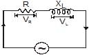
VR(t) = i0 Rsin ωt
VL(t) = i0 XL sin (ωt + p/2)
hence we can write
V(t) = i0R sin ωt + i0 XL sin (ωt + p/2)
V0 = i0
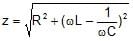
where is known as impedence (z) of the circuit.
now we can write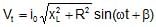
where tan β=
hence β =
Ex.6 When 100 volt dc is applied across a coil, a current of 1 amp flows through it; when 100 V ac of 50 Hz is applied to the same coil, only 0.5 amp flows. Calculate the resistance of inductance of the coil.
Sol. In case of a coil, i.e., L - R circuit.
i =  with Z =
  =
= 
So when dc is applied, ω = 0, so z = R
and hence i =  i.e., R =
  =
=  = 200 ?
 i.e., ω2L2 = Z2-R2
i.e., (2πfL)2 = 2002 - 1002 = 3 × 10⁴ (as ω = 2πf)
So, L =  =
=  = 0.55 H
Ex.7 A 12 ohm resistance and an inductance of 0.05/p henry with negligible resistance are connected in series. Across the end of this circuit is connected a 130 volt alternating voltage of frequency 50 cycles/second. Calculate the alternating current in the circuit and potential difference across the resistance and that across the inductance.
Sol. The impedance of the circuit is given by
Z =  =
= 
= 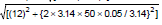 =
=  = 13 ohm
Current in the circuit i = E/Z =  = 10 amp
Potential difference across resistance
VR = iR = 10 × 12 = 120 volt
Inductive reactance of coil XL = ωL = 2πfL
Therefore, XL = 2π × 50 ×  = 5 ohm
Potential difference across inductance
VL = i × XL = 10 × 5 = 50 volt
Series C-R Circuit
Now consider an ac circuit consisting of a resistor of resistance R and an capacitor of capacitance C in series with an ac source generator.
Suppose in phasor diagram current is taken along positive x-direction. Then VR is also along positive x-direction but VC is along negative y-direction as potential difference across a capacitor in ac lags in phase by 90º with the current in the circuit. So we can write,
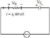
VR = I0 R sin ωt 
Potential difference across capacitor
Potential at any instant t

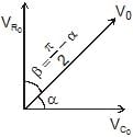
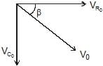
V(t) = V0 sin (ωt + b)
tan α = 
Ex.8 An A.C. source of angular frequency w is fed across a resistor R and a capacitor C in series. The current registered is i. If now the frequency of the source is changed to ω/3 (but maintaining the same voltage), the current in the circuit is found to be halved. Calculate the ratio of reactance to resistance at the original frequency.
Sol. At angular frequency w, the current in R-C circuit is given by
irms = 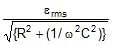 ...(i)
When frequency is changed to ω/3, the current is halved. Thus
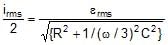 =
=  ...(ii)
From equations (i) and (ii), we have
 =
= 
Solving this equation, we get 
Hence, the ratio of reactance to resistance is 
Ex.9 A 50 W, 100 V lamp is to be connected to an ac mains of 200 V, 50 Hz. What capacitance is essential to be put in series with the lamp?
Sol. As resistance of the lamp R =  = 200 ? and the maximum current i =
  =
=  =
=  ; so when the lamp is put in series with a capacitance and run at 200 V ac, from V =iZ we have,
Z =  =
=  = 400?
Now as in case of C-R circuit, Z =  ,
,
i.e., R2 +  = 160000
or,  = 16 × 104 - (200)2 = 12 × 104
So,  =
=  × 102
× 102
or C = 
i.e., C =  = 9.2 μF
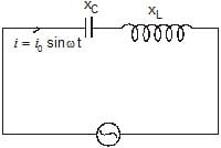
L.C. Circuit
As shown in figure a capacitor and inductance are connected in series method and alternating voltage is applied across the circuit.
Let Xc is capacitance reactance,
XL is Inductance reactance,
i = i0 sin wt current flowing through the circuit
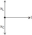
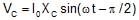
VC(t) = i0 XC sin (ωt - π/2)
VL(t) = i0 XL sin (ωt + π/2)

= i0 XC sin wt cos π/2 - i0 XC cos wt sin π/2 + i0 XL sin wt cos π/2 + i0 XL cos wt sin π/2
= i0 cos w t(XL - XC)
V(t) = V0sin (wt + p/2)
V0 = i0Z 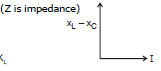
Z = (XL - XC)
cos  = 0
= 0
VCO = i0 XC ; 
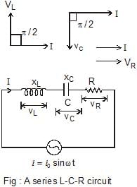
Series L-C-R Circuit
Now consider an ac circuit consisting of a resistor of resistance R, a capacitor of capacitance C and an inductor of inductance L are in series with an ac source generator.
Suppose in a phasor diagram current is taken along positive x-direction. Then VR is along positive x-direction, VL along positive y-direction and VC along negative y-direction, as potential difference across an inductor leads the current by 90° in phase while that across a capacitor, lags by 90°.
V = 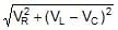
L - R - C circuit
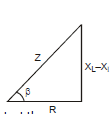
Impedance phasor of above circuit

& Impedance triangle
here B is phase angle By triangle tan β= 
Power factor cos =
= 
Let I be the current in the series circuit of any instant then
(1) Voltage V(t) = V0 sin (ωt + β) = i0 z sin (ωt + β)
here v0 = i0z & vrms = irmsz
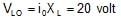
(2) 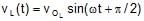 here voltage VL across the inductance is ahead of current I in phase by π/2 rad

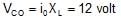
(3) VC(t) = VO C sin (ωt - π/2)
here voltage VC across the capacitance lags behind the current I in phase by π/2 rad

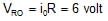
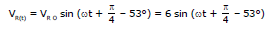
(4) VR(t) = i0 R sin ωt
here voltage VR across the resistor R has same phase as I
VO R = IO R
Special Case :
(1) When XL > XC or VL > VC then emf is ahead of current by phase β which is given by
tan β =  or cos f =
The series LCR circuit is said to be inductive
(2) When XL < XC or VL < VC then current is ahead of emf by phase angle β which is given by
 or
or 
The series LCR circuit is said to be capacitive
(3) When XL = XC or VL = VC, b = 0, the emf and current will be in the same phase. The series LCR circuit is said to be purely resistive. It may also be noted that
 or
or  or IRms =
Susceptance : The reciprocal of the reactane of an a.c. circuit is called its susceptance.
Admittance : The reciprocal of the impedance of an a.c. circuit is called its admittance.
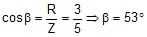
Ex.10 Figure shows a series LCR circuit connected to a variable voltage source V = 10 sin (ωt + p/4) ;
xL = 10 ?, XC = 6 ?, R = 3 ?
Calculate Z, i0, irms, vrms, VL O, VC O, VR O, b,
VL Rms, VC Rms, VRms, i(t), VL(t), Vc(t), and VR(t)
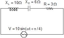 XL > XC
Sol. V = 10 sin (wt + p/4) so V0 = 10 volt
Vrms = 
Therefore, Z = 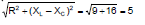


 ;
; 
 ;
; 
 ;
; 
i(t) = 20 sin (ωt + π/4 - 53°)
VL(t) = 20 sin (ωt + π/4 - 53° + π/2)
= 20 sin (ωt +  - 53° -
  ) = 12 sin (ωt -
  - 53°)
Ex.11 A resistor of resistance R, an inductor of inductance L and a capacitor of capacitance C all are connected in series with an a.c. supply. The resistance of R is 16 ohm and for a given frequency the inductive reactance of L is 24 ohm and capacitive reactance of C is 12 ohm. If the current in the circuit is 5 amp., find
(a) the potential difference across R, L and C (b) the impedance of the circuit
(c) the voltage of a.c. supply (d) phase angle
Sol. (a) Potential difference across resistance
VR = iR = 5 × 16 = 80 volt
Potential difference across inductance
VL = i × (wL) = 5 × 24 = 120 volt
|
74 videos|314 docs|88 tests
|
FAQs on Alternating Current Chapter Notes - Physics Class 12 - NEET
| 1. What is the difference between average value and RMS value of alternating current? |  |
| 2. How is power calculated in an AC circuit? | |
| 3. What are the characteristics of a series L-R circuit in AC? | |
| 4. What is a series C-R circuit and its significance in AC analysis? | |
| 5. What is the behavior of an L-C circuit in an AC environment? | |


Summary
,MCQs
,Free
,Exam
,past year papers
,Alternating Current Chapter Notes | Physics Class 12 - NEET
,Previous Year Questions with Solutions
,ppt
,Semester Notes
,Important questions
,study material
,Alternating Current Chapter Notes | Physics Class 12 - NEET
,practice quizzes
,Alternating Current Chapter Notes | Physics Class 12 - NEET
,Viva Questions
,Objective type Questions
,video lectures
,shortcuts and tricks
,Sample Paper
,mock tests for examination
,Extra Questions
;


Chapter Notes: Alternating Current Free PDF Download
Importance of Chapter Notes: Alternating Current
Chapter Notes: Alternating Current
Chapter Notes: Alternating Current NEET Questions
Study Chapter Notes: Alternating Current on the App
|
© EduRev
|
Education Revolution
|


|


