Transformers- 1


Introduction
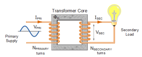
Transformer is a static device that transfers electrical energy from one electrical circuit to another by means of a magnetic field without any change in frequency. It is an electromagnetic energy-conversion device in which the energy supplied to the primary winding is first converted into magnetic energy in the core and then reconverted to useful electrical energy in the secondary (or other) winding(s). The primary and secondary windings are electrically isolated and coupled magnetically.
- Transformer operation enables economical transmission and distribution of alternating-current (a.c.) power; this is the principal reason for the widespread use of a.c. systems rather than d.c. systems.
- Transformers permit change of voltage and current levels between circuits while keeping the supply frequency unchanged.
Important Tasks Performed by Transformers
- Step-up or step-down of voltage and current levels between circuits (one or more output windings) for low- and high-current applications.
- Impedance matching between a source and its load to obtain maximum power transfer in electronic and control circuits.
- Electrical isolation: preventing d.c. from passing between two circuits while allowing a.c. transfer, and isolating one circuit from another for safety and noise reduction.
Transformer Construction
Transformers are classified by the arrangement of windings on the magnetic core. The two principal types are core-type and shell-type. These types differ in the manner in which the windings are arranged relative to the magnetic core.
Core-type Transformer
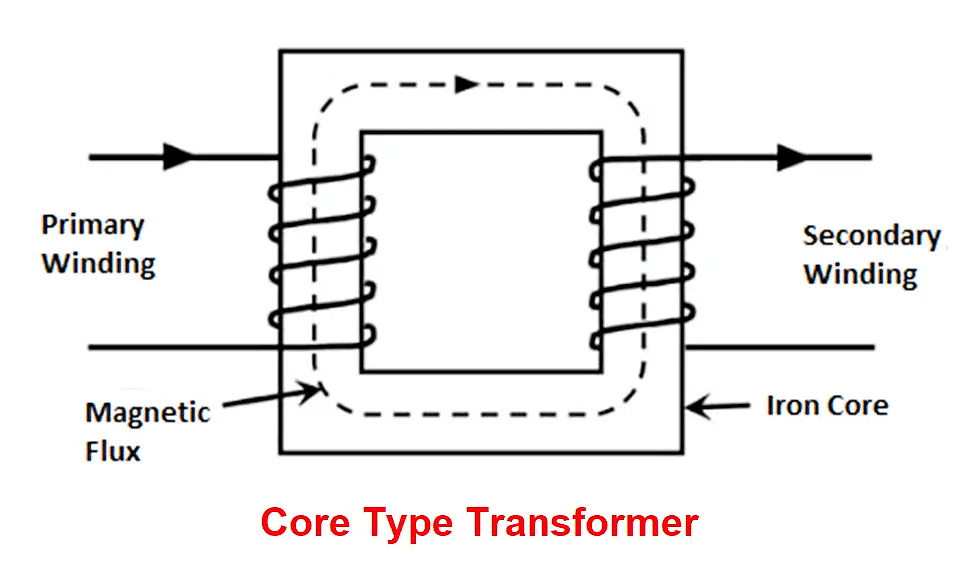
- In the core type, the windings surround a substantial part of the steel core (windings placed on separate limbs).
- For a given rating, core-type construction generally requires less iron but more conductor material than the shell type.
- Most flux is confined to the high-permeability core; some leakage flux may pass through the core legs and surrounding non-magnetic regions. To reduce leakage flux, half of the low-voltage winding may be placed on one limb and the other half on the second limb; the high-voltage winding is similarly divided as required.
- Low-voltage (L.V.) windings are usually placed next to the steel core with high-voltage (H.V.) windings outside them; this minimises insulation requirements.
- Core-type construction is preferred for high-voltage, high-power transformers.
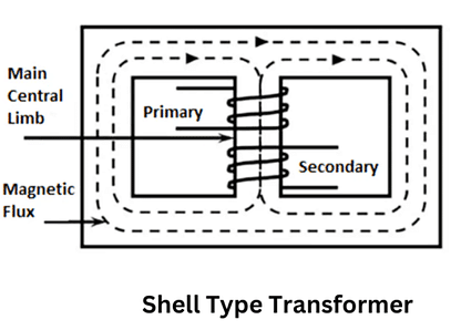
Shell-type Transformer
In the shell type, both L.V. and H.V. windings are wound over the central limb and are often interleaved or sandwiched. This arrangement gives better leakage flux control and mechanical protection to windings. Shell-type transformers are commonly used for lower-voltage, lower-power applications where compactness and short magnetic path are advantageous.
Remember:
- Small transformers are usually air-cooled; large power transformers are immersed in insulating oil for improved cooling and electrical insulation.
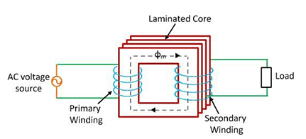
- Magnetic cores are built from stacks of thin silicon-steel laminations (about 0.35 mm thick for 50 Hz machines) to restrict eddy current circulation within individual laminations.
- Laminations are insulated from each other, typically by a thin coating of varnish, to reduce eddy-current loss.
- Cold-rolled grain-oriented (CRGO) silicon-steel sheet is widely used for transformer cores; when magnetised along the rolling direction it offers low core loss and high permeability.
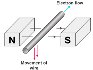
Principle of Transformer Action
- Transformer operation is based on electromagnetic induction between coupled coils.
- An electromotive force (e.m.f.) is induced in a coil whenever the magnetic flux linking the coil changes with time (Faraday's law).
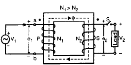
- When the primary winding P is connected to an alternating voltage source, an alternating current I0 flows through N1 turns of the primary.
- The alternating magnetomotive force (mmf) N1·I0 produces an alternating magnetic flux Φ that is confined mainly to the high-permeability iron path (core).
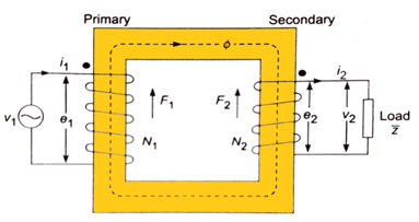
- The time-varying flux induces e.m.f. E1 in the primary and E2 in the secondary winding by mutual induction.
- When a load is connected across the secondary, a current flows in the secondary circuit and the transformer delivers power to that load.
Ideal Transformer
An ideal transformer is a simplified model used for analysis. It possesses the following idealised properties:
- Infinite magnetic permeability of the core (so negligible magnetising mmf is required).
- Zero winding resistance (no copper losses).
- Zero core losses (no hysteresis or eddy-current losses).
- All flux is confined to the magnetic core (no leakage flux).
Working Function
Consider an ideal transformer with primary applied voltage V1 and the secondary open-circuited. If V1 is sinusoidal, the no-load current I0 will also be sinusoidal. The mmf N1·I0 produces the core flux Φ which follows the time variation of I0 and thus varies sinusoidally.
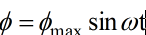
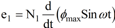
Let the alternating flux be sinusoidal and described by the expression Φ(t) = Φmax sin(ωt).
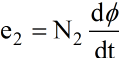
The e.m.f. e1 induced in the primary having N1 turns by the alternating flux is given by Faraday's law (expressed here conceptually):
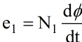
The sign and direction of the induced e.m.f. are determined by Lenz's law. The induced e.m.f. opposes the change of flux that produced it.
Try yourself: What are the two general types of transformers based on their construction?
Lenz's Law
The direction of the induced e.m.f. is such that, if it were to produce a current, the magnetic effect of that current would oppose the cause (the change of flux).
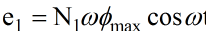
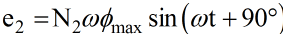
The induced e.m.f. in the primary can be expressed with a phase relation to the flux. If the flux is Φ = Φmax sin(ωt), the induced e.m.f. e1 is shifted in phase by 90°:
e1 = E1max sin(ωt + 90°)
RMS and emf per turn
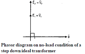
- The induced e.m.f. in the primary is 90° ahead of the core flux in phase.
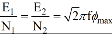
- The r.m.s. value of the induced e.m.f. E1 in the primary winding is related to frequency, number of turns N1 and maximum flux Φmax by the standard equation:
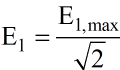
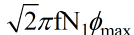
- Or summarized: E1 = 4.44 f N1 Φmax, where f is the frequency in hertz (for sinusoidal flux).
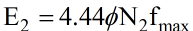
- The e.m.f. induced in the secondary winding follows the same relation (with N2 turns):
- The r.m.s. value of induced e.m.f. in the secondary is:
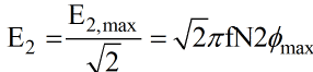
- From these relations the e.m.f. per turn is the same for primary and secondary:
- For an ideal transformer with zero winding resistances, induced e.m.f. equals terminal voltage, that is E1 = V1 and E2 = V2 (no internal drops).
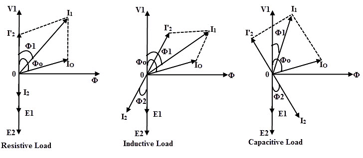
- When a load impedance ZL is connected across the secondary, a secondary current I2 flows. According to Lenz's law, the secondary mmf F2 opposes the mutual flux Φ.
- To keep the core flux Φ approximately constant, the primary must draw an additional current I'1 such that the primary mmf N1·I'1 balances the secondary mmf N2·I2:
I'1·N1 = I2·N2
- Thus the compensating primary mmf equals the secondary mmf; I'1 is called the load component of the primary current.
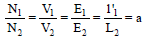
Defining a = N1/N2 as the turns ratio (voltage ratio), any change in the secondary current is immediately accompanied by an automatic change in the primary current so that the core flux remains essentially constant and independent of load current.
- Because an ideal core is assumed to have infinite permeability, the magnetising current required to establish the core flux is taken as zero in the idealised model.
Applications and Practical Notes
- Transformers are used widely to step up voltages for efficient long-distance transmission and to step down voltages for safe local distribution and utilisation.
- In electronic equipment, small transformers are used for impedance matching and isolation between circuits.
- Practical transformers depart from the ideal model: finite permeability requires a magnetising current; windings have resistance producing copper losses; core materials have hysteresis and eddy-current losses; and leakage flux causes imperfect coupling. These factors motivate the use of equivalent circuit models and loss calculations in later study.
- Constructional choices (core vs shell, lamination thickness, use of CRGO steel, cooling by oil or air) are made based on voltage, power rating, frequency and service conditions.
Summary: A transformer transfers a.c. power between electrically isolated circuits by mutual induction in a magnetic core. The induced voltages depend on turns and flux; turns ratio determines voltage transformation and related current relations ensure net mmf balance so that core flux remains essentially constant under load.
FAQs on Transformers- 1
| 1. What is the basic working principle of a transformer and how does it step up or step down voltage? |  |
| 2. Why do transformers only work with AC current and not DC? | |
| 3. What's the difference between ideal and real transformers, and why does efficiency matter in SSC JE exams? | |
| 4. How do you calculate the secondary voltage and current using the turns ratio in transformer problems? | |
| 5. What are the main causes of transformer losses and how do iron loss differ from copper loss? | |


 | Explore Courses for Electrical Engineering (EE) exam |
 | Get EduRev Notes directly in your Google search |