Polyphase Synchronous Machines - 1


Introduction
Rotating machines that rotate at a speed fixed by the supply frequency and the number of poles are called synchronous machines.
A three-phase synchronous machine is a doubly-excited AC machine: its field winding (rotor) is energised from a DC source (for example DC exciter, static excitation) and its armature winding (stator) is connected to the AC supply or load.
Under steady-state conditions the operating speed of a synchronous machine depends on the frequency of the armature current and the number of field poles.
Synchronous speed
The synchronous speed of a machine relates electrical frequency and number of poles.
Formula (rotational speed):
ns (rps) = 2 f / P
Alternative (rpm): ns (rpm) = 120 f / P
Where P = number of field poles, f = supply frequency (Hz), and ns = synchronous speed.

Remember:
- In a synchronous machine the three-phase armature winding is on the stator and the field winding is on the rotor.
Constructional Features
Synchronous machines are designed so that the stator carries the armature winding and the rotor carries the field winding. There are two common mechanical arrangements for AC rotating machines: (a) rotating field and stationary armature, (b) rotating armature and stationary field. Modern large alternators typically use rotating field and stationary armature for practical advantages.
- With armature on the stator and field on the rotor only two slip rings are required to transfer DC excitation to the rotor; this is simpler and more reliable than transferring large AC power on the rotor.
- Stationary armature windings can be insulated to higher voltages more conveniently than rotating windings.
- Stationary armature windings allow more efficient cooling arrangements.
- Field winding on the rotor is low-power (DC) and requires less copper and insulation; this reduces rotor weight and inertia and permits higher permissible rotor speeds for a given centrifugal stress.
- Placing high-voltage three-phase armature windings in the stator slots makes the machine bracing and mechanical support simpler and more rigid against electromagnetic forces.
Rotor types
Synchronous machines are classified by rotor geometry:
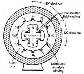
- Salient-pole type - poles are projecting ("salient"). Field winding on each pole is generally a concentrated winding. The air-gap is non-uniform (smaller under pole faces, larger between poles).
- Cylindrical (round) rotor type - rotor surface is nearly cylindrical; field winding is distributed in rotor slots. The air-gap is approximately uniform (neglecting slot openings). This type is used for high-speed machines (steam-turbine driven alternators).
Synchronous generators are usually three-phase because of advantages in generation, transmission and utilisation of power. For three-phase generation at least three coils displaced by 120 electrical degrees in space are required.
Generated emf in Armature
In a rotating machine the relative motion between an armature coil and the flux-density wave causes time variation of flux linkage and an induced emf in the coil.
- Let ø be the total flux per pole and kw be the winding distribution factor (since armature winding is distributed); the induced emf expression contains kw.
- The generated phase emf in a synchronous machine is proportional to flux per pole and speed, and is reduced by winding factors.
Field Winding (Rotor)
The field winding of a synchronous machine is always energised with direct current under steady-state operation.
Field current relation:
If = Vf / rf
Where Vf is the DC field voltage and rf is the field winding resistance.
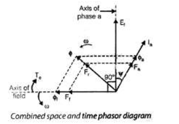
Flux and MMF Phasors
We use phasor diagrams in space and time to represent the relationships between field mmf, armature mmf, fluxes and induced emfs. The following discussion is primarily for cylindrical-rotor machines where the air-gap is essentially uniform and phasor addition of mmfs is straightforward.
- The no-load terminal voltage of an alternator is adjusted to rated value by varying the field current.
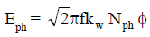
- The emf generated by a flux (field) lags that flux by 90° in time: the induced voltage is 90° behind the flux wave which creates it. Thus Ef lags øf by 90°.
- Field mmf per pole Ff = If Nf (neglecting saturation the flux øf is in phase with field mmf Ff).
Case 1 - No-load / Excitation
The emf produced by the field flux alone is called the excitation voltage.
When Alternator is Connected to Balanced 3-Phase Load
- Balanced three-phase generated emfs result in balanced armature currents.
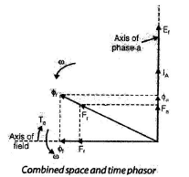
- At unity power factor the armature current Ia and excitation voltage are maximum at the same instant; armature mmf produced is perpendicular to the field flux and therefore is cross-magnetising.
- The mmf set up by armature current is called armature-reaction mmf Fa.
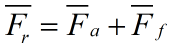
- The phasor sum Ff + Fa gives the resultant air-gap mmf Fr.
- For generator operation the prime-mover torque must oppose the electromagnetic torque produced.
Case 2 - Unity power-factor load
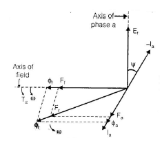
Case 3 - Zero power-factor (lagging) load
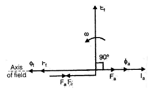
- When load power factor is zero and lagging, the armature mmf produced opposes the field mmf (demagnetising effect).
- Ef lags øf by 90°, Ia lags Ef by 90°, therefore Fa opposes Ff.
- Under this condition the armature mmf is entirely demagnetising in nature for a generator.
Case 4 - Zero power-factor (leading) load
- For zero power-factor leading the armature mmf is entirely magnetising in nature (it aids the field mmf).
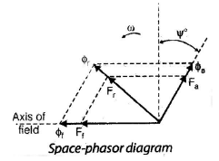
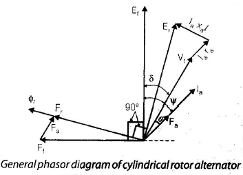
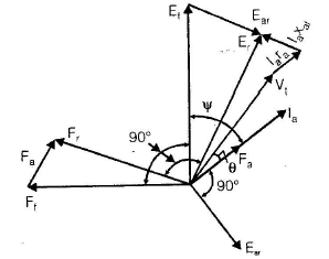
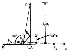
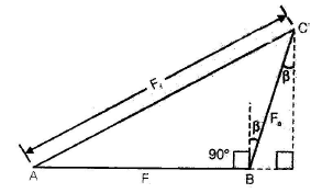
Case 5 - General lagging power-factor load
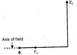
Let armature current Ia lag the excitation voltage Ef by an electrical angle ψ. Then the armature reaction mmf Fa lags the field mmf Ff by a space angle of (90° + ψ). The resultant mmf Fr is the phasor sum of Ff and Fa. The current Ia lags Ef by ψ because load power factor measured with respect to Ef is cos ψ lagging.
Cylindrical-rotor Synchronous Motor
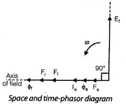
- In motor operation the rotating armature mmf phasor Fa is in phase with Ia and the armature-reaction flux øa is in phase with Fa.
- The resultant mmf Fr is the phasor sum of Ff and Fa. For motor operation the field poles must be dragged behind the resultant air-gap flux by the load torque.
When Ia lags Ef by 90°, in an alternator the armature mmf is magnetising; in a synchronous motor it is demagnetising.
Cylindrical Rotor Alternator - Resultant Flux
- The air-gap flux actually present is due to the resultant mmf of field and armature currents.
- For cylindrical rotors the phasor addition of field mmf Ff and armature mmf Fa is valid because both mmfs are approximately sinusoidally distributed and there is no relative motion between their spatial patterns at synchronous speed.
Open-Circuit and Short-Circuit Characteristics
These tests are essential for finding machine parameters and predicting performance.
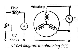
Open-Circuit Characteristic (OCC)
Drive the alternator at rated speed with armature open-circuited and increase field current from zero while noting the terminal voltage. Plot terminal voltage (generated emf) versus field current (or field mmf).
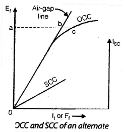
- At small field current the iron requires negligible mmf so nearly all applied mmf appears across the air-gap; the OCC is approximately linear for small excitations.
- As field mmf increases iron parts require growing mmf (saturation) and the OCC curve bends and becomes nonlinear.
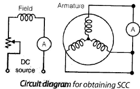
Short-Circuit Characteristic (SCC)
Drive the alternator at rated speed and short-circuit the armature terminals through an ammeter. Increase field current and note the short-circuit armature current.
- During the short-circuit test the machine typically operates under unsaturated conditions and SCC is approximately a straight line.
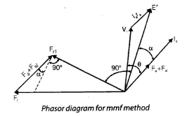
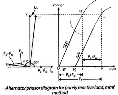
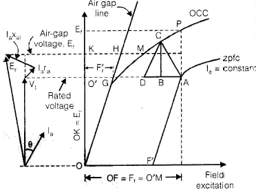
Zero Power-Factor Characteristic and Potier Triangle
The zero-power-factor characteristic (ZPFC) is the plot of armature terminal voltage versus field current when the machine supplies a fixed armature current at essentially zero (purely inductive) power factor. ZPFC combined with OCC is used to find armature leakage reactance Xal and armature reaction mmf Fa.
- Procedure to obtain ZPFC: run machine at rated speed, connect a purely inductive load, increase field current until full-load armature current flows, and record terminal voltage. Vary load in steps and adjust field to maintain full-load current; plot terminal voltage versus field current.
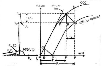
In the zero-power-factor lagging condition the terminal voltage Vt and air-gap voltage Er are nearly in phase and satisfy the approximate relation
Vt = Er - Ia Xal
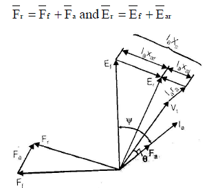
The resultant mmf Fr and field mmf F1 are related by simple algebraic relations on the potier diagram.
Voltage Regulation of an Alternator
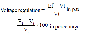
Voltage regulation is the change in terminal voltage when the machine goes from no-load to full-load at constant speed and field excitation. In large machines it is difficult to load them to rated output for direct measurement, so test methods are used to determine machine constants and compute regulation.
Methods for Computing Voltage Regulation
Electromotive Force (emf) Method (Synchronous impedance method)
This is also known as the synchronous impedance method. It can be applied readily to cylindrical-rotor synchronous machines because the resultant air-gap flux is not affected by rotor angular position.
Assumptions:
- Magnetic circuit iron is assumed to have constant permeability (saturation neglected).
- mmfs can be treated as proportional to corresponding fluxes and thus to induced emfs.
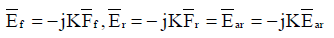
Field mmf Ff generates an emf Ef which lags Ff by 90°. Similarly resultant mmf Fr generates air-gap voltage Er lagging Fr by 90°, and armature-reaction mmf Fa generates Ear lagging Fa by 90°.
Define a constant K (slope of the air-gap line) and a constant C so that armature-reaction mmf is proportional to Ia. The armature-reaction effect can be represented as an equivalent emf or as an equivalent reactance.

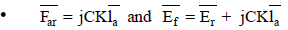
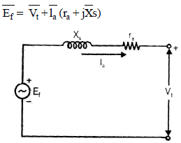
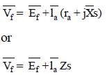
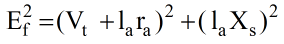
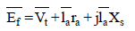
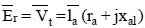
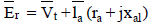
In phasor form the air-gap emf Er is given by the phasor sum of terminal voltage Vt, armature drop Ia ra and reactive drop Ia Xal.
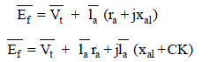
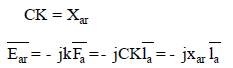
By grouping constants we obtain an equivalent reactance due to armature reaction Xar. The total synchronous reactance
Xs = Xal + Xar
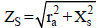
and the per-phase synchronous impedance
Zs = ra + j Xs
Xar is a fictitious reactance that accounts for the voltage generated by armature-reaction mmf. The term (ra + j Xs) is called the synchronous impedance.
Remember: for an alternator the current and power leave the machine; for a synchronous motor the current and power enter the machine.
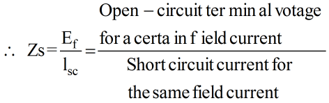
Measurement of Zs and Xs
- Open-circuit (OCC) and short-circuit (SCC) characteristics are required to determine Zs and Xs.
- In the open-circuit test the armature current is zero so Vt = Ef (the generated emf equal to terminal voltage).
- In the short-circuit test the entire emf Ef is consumed in circulating the short-circuit current Isc through synchronous impedance Zs.
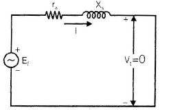
In the short-circuit test the phasor diagram shows Ef across Zs carrying Isc.
Note: If there were no saturation Zs would be constant. In practice Zs varies and decreases as saturation increases on the OCC.
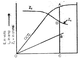
For voltage regulation calculations one value of Zs must be chosen; the lowest value (from largest possible short-circuit current) is commonly used which gives a conservative estimate for regulation by emf method.
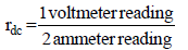
Armature resistance and effective resistance
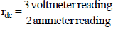
- The dc resistance rdc of one phase is measured by voltmeter-ammeter method.
- If the armature winding is star-connected and neutral is not available, use the appropriate formula for conversion.
The effective armature resistance per phase in AC operation is larger than the measured DC resistance due to skin effect and heating; approximate relation commonly used is
ra = (1.2 to 1.3) rdc
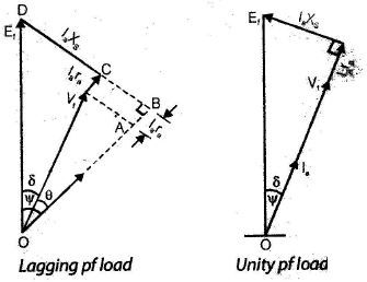
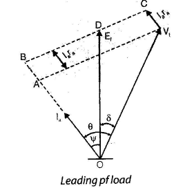
Phasor diagrams differ for lagging, leading and unity power-factor loads. Representative diagrams are:

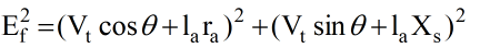
The percentage voltage regulation is calculated from phasor relations and usually expressed as:
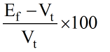
NOTE: Because the emf method uses the unsaturated synchronous impedance it tends to give a higher (pessimistic) value of voltage regulation than the actual value since under load the machine flux paths are more saturated and effective reactance is lower.
The Magnetomotive-Force (mmf) Method
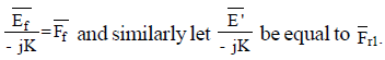
This method replaces emfs by equivalent mmfs (assumes uniform air-gap and neglects saturation). The voltage equation of an alternator can be converted into an mmf equation by dividing by a suitable constant.
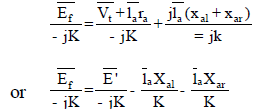
- The field mmf Ff induces an emf Ef lagging it by 90°; resultant mmf Fr induces an emf E′ lagging Fr by 90°.
- The armature-reaction mmf is in phase with Ia; the armature-reaction reactance drop Ia Xar can be transformed into an equivalent mmf Fa.
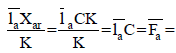
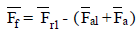
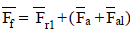
Note: The combined mmf (Fal- + Fa) is in phase with armature current Ia.
Let α denote the angle by which Ia lags E′ and also the angle between the normal line of Fr1 and (Fa + Fal).
To obtain voltage regulation by the mmf method:
- Plot OCC and SCC.
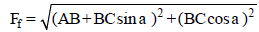
- Find the required point on the OCC corresponding to the resultant air-gap mmf Fr1 obtained from SCC.
- Find (Fa + Fal) from SCC.
- Calculate the required phasor relationships and obtain field mmf Ff.

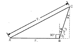
Corresponding to Ff, obtain Ef from OCC and thus compute the voltage regulation of the alternator.
Zero Power-factor Method (Potier method)
- This method handles emfs as voltages and mmfs as field ampere-turns.
- The armature reaction mmf Fa and armature leakage reactance Xal are determined from the Potier triangle constructed using OCC and ZPFC.

Remember: ZPFC method requires OCC and ZPFC and gives accurate results for voltage regulation.
New ASA (American Standards Association) Method
This method is a modification of the mmf method and gives satisfactory results for both cylindrical and salient-pole machines. It requires OCC and ZPFC and only two points on the ZPFC are sufficient (points labelled A and F′ on a standard construction).
- Point A is obtained by loading the over-excited alternator with an under-excited synchronous motor until full-load armature current at rated voltage flows.
- Point F′ is the field excitation required to circulate full-load armature current when the alternator is short-circuited.
- Armature leakage reactance Xal is determined from the Potier reactance drop BC on the potier triangle.
Using the potier triangle and OCC allows determination of the air-gap voltage Er, the saturation effect and the total field mmf Ff, leading to Ef and the voltage regulation.
Saturation Synchronous Reactance Method
In the emf and mmf methods saturation was neglected. In practice the magnetic circuit is partially saturated under load. The effect of saturation can be included by introducing a saturation factor k which modifies the magnetising (armature-reaction) reactance only.
- The synchronous reactance XS consists of leakage reactance Xal (practically unaffected by saturation) and armature-reaction reactance Xar (affected by saturation): XS = Xal + Xar.
- Apply saturation factor k to Xar to obtain the saturated synchronous reactance Xss. The leakage reactance Xal remains unchanged.
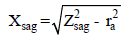
The unsaturated synchronous reactance Xsag can be calculated for any field current from OCC and SCC data and then Xar = Xsag - Xal.
Procedure to use the saturated synchronous reactance method:
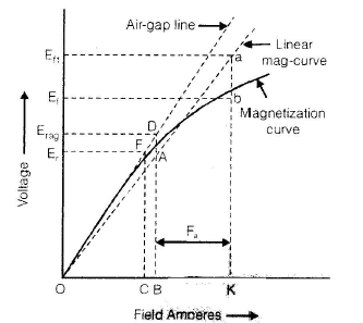
- Compute air-gap voltage Er for the operating condition.
- Mark Er on the OCC and find corresponding unsaturated air-gap voltage on the air-gap line.
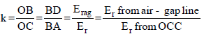
- Obtain saturation factor K as ratio of saturated to unsaturated values (BD/BA in the standard diagram).
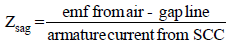
- Calculate Xsag (unsaturated synchronous reactance).
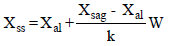
- Find saturated synchronous reactance Xss = Xal + k Xar.
- Draw phasor diagram replacing Xs by Xss, compute Ef and obtain voltage regulation.
Practical Notes and Summary Points
- The generated emf in a phase lags the flux that produces it by 90°.
- Armature reaction may be cross-magnetising, demagnetising or magnetising depending on load power factor.
- OCC, SCC and ZPFC are the principal characteristic curves used for machine parameter extraction.
- Synchronous reactance Xs = Xal + Xar; synchronous impedance Zs = ra + j Xs.
- Emf (synchronous-impedance) method tends to overestimate (pessimistic) voltage regulation because it ignores saturation under load.
- More accurate regulation calculations use mmf/Potier/ZPFC-based methods or include a saturation correction (saturation synchronous reactance method).
- Effective armature resistance in AC can be approximated by ra ≈ (1.2 to 1.3) rdc to account for skin effect and heating.
FAQs on Polyphase Synchronous Machines - 1
| 1. What is a polyphase synchronous machine? |  |
| 2. How does a polyphase synchronous machine differ from other types of electrical machines? | |
| 3. What are the main applications of polyphase synchronous machines? | |
| 4. How does the excitation of a polyphase synchronous machine affect its performance? | |
| 5. What are the advantages of using polyphase synchronous machines in power systems? | |


 | Explore Courses for Electrical Engineering (EE) exam |
 | Get EduRev Notes directly in your Google search |