Polyphase Synchronous Machines - 2


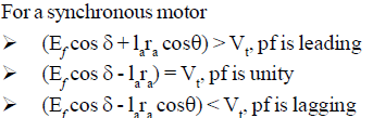
SYNCHRONOUS MOTOR PHASOR DIAGRAM
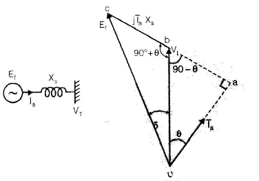
The phasor diagram for a synchronous machine links the internal induced emf, the terminal voltage and the armature reaction drop. The per-phase voltage equation of a synchronous motor/generator may be written in phasor form as an internal emf plus the synchronous reactance drop equals the terminal voltage.
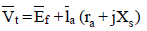
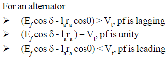
Remember: For an alternator the internal emf Ef is normally ahead of the terminal voltage Vt, just as the field poles lead the rotor electrical angle. For a synchronous motor the internal emf Ef is behind the terminal voltage Vt, i.e. the field poles lag the rotor electrical angle.
Phasor diagrams for different power factors
Phasor arrangements change with the power factor of the load on the machine. Representative phasors for the armature current and resulting relations are:
- For lagging power factor:

- For unity power factor:
- For leading power factor:

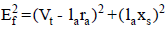
POWER FLOW THROUGH AN IMPEDANCE
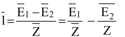
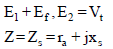
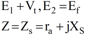
Consider two AC sources E1 and E2 connected through an impedance Z∠θZ. Current I flows from the higher potential source to the lower; the phase relationships determine active and reactive power flow.

P = VIcosθ Q = VI sinθ
Alternatively the phasor/ algebraic representation of currents and voltages may be shown as:
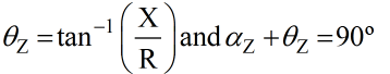
The impedance angle θZ is given by the arctangent of reactance over resistance:
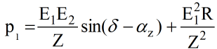
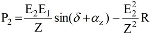
Active power
Active power at the source end equals the product of the source voltage and the component of current in phase with that voltage.
Active power at the load end equals the product of the load voltage and the component of current in phase with the load voltage.
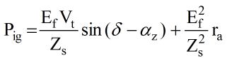
POWER FLOW IN A CYLINDRICAL-ROTOR SYNCHRONOUS MACHINE
Power flow diagrams show electrical input, electrical output and mechanical quantities for both generator and motor modes.
Power input to a generator (electrical input at generator terminals):
Power output of a generator (mechanical power at shaft delivered):
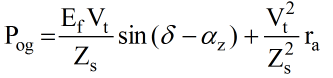
For a cylindrical-rotor synchronous motor:
Power input to the motor (electrical input at terminals):
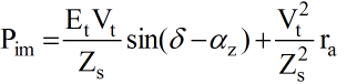
Power output of the motor (mechanical power at the shaft):
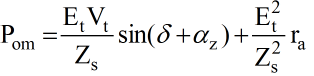
Note: The mechanical power available at the shaft of a synchronous motor equals the gross mechanical power developed Pom minus rotational losses (friction, windage and core losses). For a generator the mechanical input to the rotor equals the electrical output plus the rotational losses.
Remember: The difference between input and output power (for either motor or generator) must equal the ohmic (I²R) armature loss Ia² ra. Usually the armature resistance ra is small and often neglected; in that case ra = 0 and the synchronous impedance becomes essentially reactance (Zs = Xs).
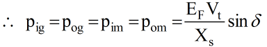
Power input to the generator is taken at the electrical terminals where the emf is Ef. The mechanical power developed in the motor Pom is measured at the same electrical terminals; hence Electrical power equations for motor and generator have similar form but differ in sign conventions and reference direction; replacing δ by -δ changes the direction of power flow but does not imply identical terminal powers in practice.
Pom = Pig
Pim = - Pog
MAXIMUM POWER CONDITIONS
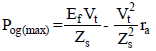
Maximum transmissible power across an impedance occurs when the load (power) angle equals the impedance angle.
For maximum power output the condition is δ = θz.
The corresponding maximum power expressions are:
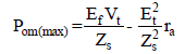
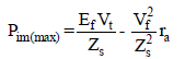
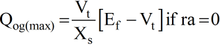
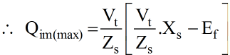
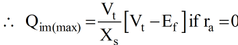
For maximum power input the load angle satisfies δ = 90° + αZ = 180° - θZ, where αZ is a related angle used in the impedances representation.
Maximum power input to generator:
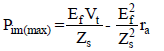
Maximum power input to motor:
REACTIVE POWER
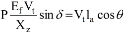
Reactive power at a terminal equals the product of the terminal voltage and the component of current in quadrature (90°) with that voltage. For a generator terminal:
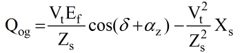
The output terminals of a generator are the input terminals for a motor; the same relations apply with proper sign conventions.
Condition for maximum reactive power
For a generator the condition for maximum reactive power is:
δ + αz = 0
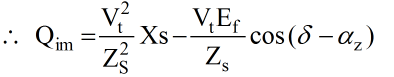
For a motor the corresponding condition is:
δ - αz = 0
When electrical power input to the motor Pim is maximum (i.e. δ = 90° + αz), the reactive power under that condition is shown as:

Generating mode (special case)
If ra = 0 then reactive power expressions simplify to the indicated forms:
Sign and excitation conventions - key points
- For a motor, positive values of active and reactive power indicate flow into the motor.
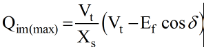
- When Ef cos δ > Vt and the machine is overexcited, Qim is negative; reactive power flows outwards and the motor delivers reactive power to the infinite bus (operating at leading power factor).
- When Ef cos δ = Vt (normally excited), the generator neither delivers nor absorbs reactive power; the power factor is unity.
- When the machine is underexcited, Qim is positive and reactive power flows into the motor; the synchronous motor operates at lagging power factor.
Additional remembered facts
- Under the condition of maximum reactive power input, Qim(max) is positive and the synchronous motor is absorbing reactive power.
- Under the condition of maximum active power input, the reactive power Qim is also positive; the machine absorbs reactive power in this case as well.
- Thus at maximum values of active or reactive power a synchronous machine always absorbs reactive power.
Note: An overexcited synchronous machine delivers reactive power; an underexcited one absorbs reactive power. With normal excitation it neither absorbs nor delivers reactive power.
POWER FACTOR CONTROL
The power factor of a synchronous machine is controlled by adjusting the field excitation. Changing field current changes the internal emf Ef, which alters the armature current phasor and therefore the power factor.
Synchronous motor - qualitative explanation
- An AC electromagnetic device requires a magnetising current from the AC source to establish working flux; this magnetising current typically lags the applied voltage by nearly 90°.
- The armature winding is excited by the AC supply while the field winding receives DC excitation. At constant terminal voltage Vt, the resultant air-gap flux demanded by the machine remains approximately constant.
- The air-gap flux results from the combined mmfs of the armature AC and the dc field winding.
- If the field current is sufficient to establish the required air-gap flux, the magnetising current drawn from the AC supply is minimal and the motor operates at unity power factor; this field setting is called normal excitation.
- If field current is less than normal (underexcited), the deficiency in flux must be supplied by the armature mmf and the armature draws lagging magnetising current; the motor runs at a lagging power factor.
- If field current is greater than normal (overexcited), the excess flux is neutralised by armature mmf and the armature current leads Vt; the motor operates at a leading power factor.
- Per-phase power relations and phasor balance depend on Ef, Xs, Vt and the armature current phasor.
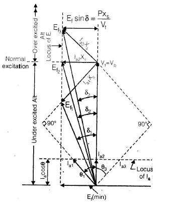
Variation of currents and angles with excitation
- For constant power output the product Ef sin δ and Ia cos θ must remain constant because Vt and Xs are (usually) constant.
- As field current (and hence Ef) varies, Ef sin δ must remain constant; therefore δ changes accordingly.
- As Ef varies the quadrature drop Ia Xs and thus armature current magnitude Ia changes such that its active component Ia cos θ remains the same for the same developed power.
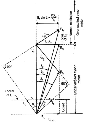
Effect of field current on synchronous motor power factor
- If excitation voltage is Ef1 the motor may be underexcited and armature current Ia1 lags Vt by power factor angle θ1. The relation Ef + jIa Xs = Vt must be satisfied.
- When excitation is increased to Ef2, δ reduces to maintain Ef sin δ constant, and armature current changes to Ia2.
- Further increase to Ef3 reduces δ to δ3, producing Ia3 so that the motor operates at a leading power factor. The active component of armature current remains equal across these excitations: Ia1 cos θ1 = Ia2 cos θ2 = Ia3 cos θ3. The armature current is minimum at unity power factor and larger for both leading and lagging pf.
- Curves joining minimum armature current points at different field currents form the unity power-factor compounding curve; similar compounding curves can be drawn for 0.8 lagging and 0.8 leading pf.
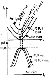
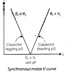
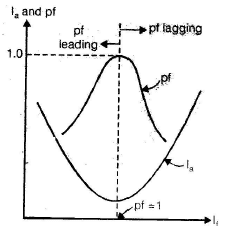
Synchronous motor V-curves and power factor versus field current
- Plotting armature current against field current at a given load produces the V-curve: armature current is minimum at the field current that yields unity pf.
- The field current required for unity pf at full load is greater than that required for unity pf at no load.
- If a synchronous motor running at full-load unity pf has its mechanical load removed, it tends to run at a leading pf.
- Plotting power factor versus field current gives an inverted-V shape, often called the inverted V-curve.
- An overexcited synchronous motor can supply leading reactive current and is therefore used to improve system power factor.
- An unloaded synchronous motor used primarily for reactive-power control (no mechanical load on shaft) is called a synchronous condenser or synchronous compensator.
- When Ia leads Vt by 90° the machine behaves like a capacitive bank; when Ia lags by 90° it behaves like an inductive bank.
ALTERNATOR CONNECTED TO AN INFINITE BUS
When an alternator is connected to an infinite bus (a large system of constant voltage), its excitation determines whether it supplies or absorbs reactive power.
- If excitation emf Ef1 is low (underexcited), the armature current Ia1 leads bus voltage Vb and the alternator absorbs reactive power from the bus.
- With excitation increased to Ef2 the armature current becomes in-phase with Vb, giving unity pf and no reactive exchange.
- For further increase to Ef3 the alternator is overexcited, Ia3 lags Vb and the alternator delivers reactive power to the bus (lagging pf).
- Underexcited alternator → lagging current
- Overexcited alternator → leading current
The plot of Ia versus field current is again a V-curve; power factor versus field current is the inverted V-curve.
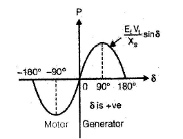
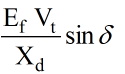
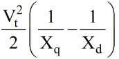
POWER-ANGLE CHARACTERISTICS - CYLINDRICAL-ROTOR MACHINE
Consider a generator feeding an infinite bus of constant voltage Vt. The per-phase delivered power depends on the power angle δ and the machine parameters.
SALIENT-POLE SYNCHRONOUS GENERATOR - PHASORS AND POWER
For salient-pole machines the air-gap and reactance are not uniform; this introduces additional harmonic terms in the developed torque and power.
The per-phase power delivered to the bus can be written in the usual V×I cosθ form:
P = Vt Ia cos θ
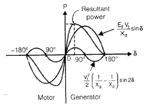
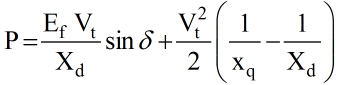
The total power often splits into a fundamental component (proportional to sin δ) and a second harmonic component proportional to sin 2δ:
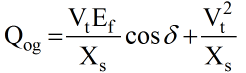
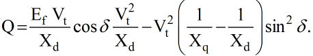
For a salient-pole synchronous generator the per-phase reactive power in terms of δ for a lagging power factor is given by:
The synchronizing power coefficient measures the stiffness of electromagnetic coupling between stator and rotor fields. A large coefficient means the rotor tends to resist speed change due to electrical disturbances; excessive stiffness would make speed nearly constant regardless of mechanical load fluctuations.
SYNCHRONOUS MACHINE STABILITY
A synchronous machine connected to an infinite bus is stable if it remains in synchronism (rotor and stator fields stay locked in step).
Stability is the tendency of the machine to develop electromagnetic forces that maintain synchronism and equilibrium.
Stability limit denotes the maximum power transfer possible while maintaining stability.
Steady-state stability limit is the maximum power flow through a system point without loss of synchronism when the power changes very slowly.
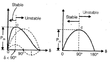
Methods to improve steady-state stability include increasing machine excitation (raise Ef), reducing reactance (for example by paralleling transmission lines) and using series capacitors to reduce effective line reactance.
HUNTING (OSCILLATIONS OF THE ROTOR)
Hunting describes the oscillatory motion of the rotor about its equilibrium position when disturbed. It is caused by imbalance between mechanical and electromagnetic torques and corresponds to the phasor Ef swinging relative to fixed terminal voltage Vt. Hunting is also called phase-swinging.
Reduction of hunting
- Provide damper windings in the pole faces to electrically damp oscillations.
- Use heavy rotating inertia (flywheels) to slow speed changes.
- Design an appropriate synchronizing power coefficient (sufficient stiffness but not excessive).
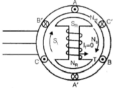
DAMPER WINDINGS
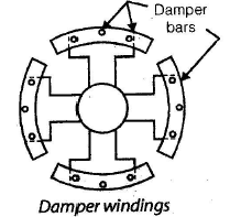
Damper windings are low-resistance copper, brass or aluminium bars embedded in slots on pole faces and short-circuited by end rings. They resemble the bars of a squirrel-cage rotor and provide induced currents when relative motion exists between stator field and rotor, producing damping torque. Sometimes interpolar connectors are omitted to make an incomplete damper winding.
Note: For damping, damper winding resistance Rd should be small; for good starting torque the bars are kept low resistance. A compromise in the resistance value meets both needs. In alternators low damper resistance minimises hunting.
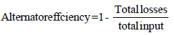
EFFICIENCY OF SYNCHRONOUS MACHINES
The principal losses in synchronous machines are:
- No-load rotational losses: friction and windage plus open-circuit core loss.
- Field circuit loss: DC field copper loss in the rotor winding.
- Direct load loss: I²R loss in the armature winding under load.
- Stray load losses: additional losses in iron and in armature conductors due to leakage flux, skin effect and circulating currents.
The combination of direct load loss and stray load losses is often called the short-circuit load loss.
Stray load loss has two main components: iron (core) loss caused by armature leakage flux and extra armature ohmic loss caused by skin effect and eddy currents in armature conductors.
Power flow diagram and maximum efficiency
No-load rotational loss may be denoted Pr and includes friction, windage and open-circuit core loss. Field circuit loss equals Vf If. Short-circuit load loss equals 3 Ia² ra plus stray load loss.
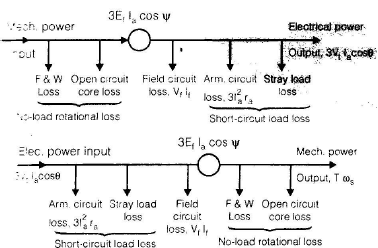
Maximum efficiency occurs when variable losses equal constant losses, i.e. when:
3 Ia² ra = Pr + Vf If
where Ia is the armature current at which maximum efficiency occurs. Total alternator losses equal friction and windage plus open-circuit core loss plus short-circuit load loss plus field circuit loss:
Total losses = Wf + W2 + W3 + Vf If
STARTING OF SYNCHRONOUS MOTOR
Synchronous motors are not self-starting because when the rotor is stationary the alternating stator field produces a torque that reverses every half cycle; the rotor cannot follow these rapid reversals unless it has starting means.
Two common starting methods are:
- Starting with the help of an external prime mover to accelerate the rotor close to synchronous speed, then applying DC field to lock in synchronism.
- Starting with the help of damper windings (squirrel-cage action) which produce an induction motor starting torque until the rotor is brought near synchronous speed, whereupon the DC field is applied to synchronise the rotor.
When the stator rotating field speed Ns is 1500 rpm (for example), at start the rotor speed Nr is zero. The stator field completes one mechanical revolution relative to rotor producing alternating torque that reverses every half revolution; the rotor inertia prevents it following these reversals, hence it remains stationary unless started externally.
Damper-winding starting: Damper bars embedded in pole shoes are short-circuited. With no DC field applied there is relative motion between stator field and damper winding, inducing currents in the bars. These induced currents create a starting torque by induction motor action and accelerate the rotor to a speed somewhat less than synchronous. Once near synchronism the DC field is excited, the stator and rotor fields lock and the machine runs at synchronous speed. In steady state there is no relative motion between damper winding and stator field, so the damper winding plays no role in steady operation.
FAQs on Polyphase Synchronous Machines - 2
| 1. What is a polyphase synchronous machine? |  |
| 2. How does a polyphase synchronous machine work? | |
| 3. What are the advantages of polyphase synchronous machines? | |
| 4. What are the applications of polyphase synchronous machines? | |
| 5. How are polyphase synchronous machines different from polyphase induction machines? | |


 | Explore Courses for Electrical Engineering (EE) exam |
 | Get EduRev Notes directly in your Google search |