Instruction Formats


Instruction Formats
The computer performs a specific task only when the necessary steps to complete the task are specified. The ordered collection of such steps forms a program. These ordered steps are called instructions. Instructions of a program are stored in main memory at particular addresses and are executed one at a time in sequence unless altered by control-transfer instructions. The control unit reads an instruction from a memory address, decodes and executes it, and then proceeds to the next instruction address until the program completes.
Instruction code structure and fields
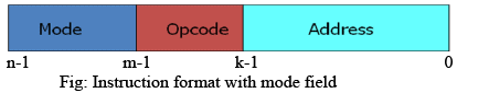
An instruction is represented by a fixed number of bits. The bits of an instruction are divided into groups called fields. Common fields in an instruction format are listed below.
- Operation code (Opcode) field - specifies the operation to be performed (for example add, subtract, load, store, shift).
- Address field - designates a memory location or a processor register where an operand resides or will be stored.
- Mode field - specifies how the operand or effective address is determined (addressing mode).
If an instruction word is n bits long, contains k bits for the address field and m bits for the opcode field, then the instruction can directly refer to 2k distinct memory/register locations and can specify 2m distinct operations.
The opcode, address and mode fields - more detail
The opcode is the portion of the instruction that tells the CPU what operation to perform. The address field gives the reference to the operand (which may be in memory or in a register). The mode field modifies the meaning of the address field and determines how the operand is to be obtained. Common addressing modes include:
- Immediate - the operand is contained in the instruction itself.
- Direct (absolute) - the instruction contains the memory address of the operand.
- Indirect - the instruction contains an address which points to a memory location that holds the effective address of the operand.
- Register - the operand is a processor register specified in the instruction.
- Register indirect - a register contains the address of the operand in memory.
- Indexed - the effective address is obtained by adding a constant (displacement) to the contents of an index register.
- Relative - the effective address is obtained by adding a signed displacement to the current program counter (useful for branching).
Whether a particular addressing mode is available depends on the instruction set architecture and the instruction format; the mode field provides the necessary specification so the control unit can form the effective address.
Types of instruction formats depending on CPU organisation
The CPU internal organisation strongly influences the instruction format and the number of address fields required by instructions. Three common CPU organisations are listed below.
Single-accumulator organisation
All arithmetic and logical operations use a single, implied accumulator register AC. The instruction format typically contains a single address field which names a memory location. The operation is performed between the accumulator and the memory operand. Example instruction: ADD X, where X is the memory address of the operand. Load and store instructions (for example LOAD X, STORE X) are used to transfer data between memory and the accumulator.
General-register organisation
The CPU has several general-purpose registers and instructions explicitly reference these registers. Typical instruction formats contain multiple register address fields. For arithmetic operations that specify three registers, an instruction may look like ADD R1, R2, R3, meaning R1 ← R2 + R3 (result in R1). This organisation supports fewer memory references in arithmetic instructions and allows compact expression of computations in registers.
Stack organisation
A stack machine uses a last-in, first-out stack for intermediate results. Computational instructions typically have no explicit address fields; they implicitly operate on the top elements of the stack. For example, the instruction ADD pops the two top values from the stack, adds them and pushes the result back on the stack. Instructions that manipulate the stack (for instance PUSH X, POP X) may require an address field to move data between memory and the stack.
Instruction classification by number of address fields
Instructions are often classified by the number of explicit address fields they contain. The common categories are three-address, two-address, one-address and zero-address instructions. Each class affects program length, instruction complexity and instruction word size.
Three-address instruction
Each instruction specifies two operand locations and a distinct result location. A conventional three-address instruction has the form:
- OP dest, src1, src2 - compute src1 OP src2 and store result in dest.


- Advantage: leads to short programs when evaluating complex arithmetic expressions because intermediate results can be placed directly into named locations.
- Disadvantage: instruction words require many bits to specify three addresses, increasing the instruction memory size and the complexity of the instruction decoder.
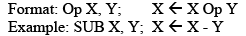
Two-address instruction
Two-address formats are common in commercial machines. Each address field may reference a register or a memory word. One of the addresses commonly serves as both a source and the destination.
- Typical form: OP src/dest, src2 - the result overwrites the first operand location.
- To preserve an operand that must not be altered, a MOV instruction is used to copy a value to a temporary or result location before performing the operation.
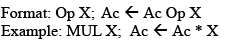
One-address instruction
One-address machines generally use an implied accumulator register AC. The instruction format contains a single address field that names a memory location. An operation is performed between the accumulator and the memory operand and the result is left in the accumulator.
- Typical forms: ADD X (AC ← AC + M[X]), LOAD X (AC ← M[X]), STORE X (M[X] ← AC).
- Advantages: simpler instruction format and smaller instruction size compared to three-address instructions.
- Disadvantages: more instructions may be needed because many intermediate results need to be moved in and out of the accumulator using LOAD/STORE operations.
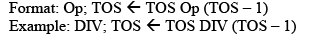
Zero-address instruction (stack machines)
Zero-address instructions do not include operand address fields for computational operations. The operands are implicitly taken from the stack top. Examples of such instructions are ADD, SUB, MUL, DIV which pop the required operands from the stack, perform the operation and push the result back. Stack manipulation instructions like PUSH and POP may require an address field to transfer data between memory and the stack.
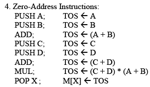
Worked example: effect of instruction format on program size
Consider the arithmetic expression X = (A + B) × (C + D). The number and form of instructions required to evaluate this expression depend on the instruction format (zero, one, two or three address). The following sequences illustrate the differences. It is assumed that the machine has two processor registers R1 and R2 where usable; the notation M[A] denotes the contents of memory at address A. A temporary memory location T may be used in formats that cannot hold all intermediate values in registers.
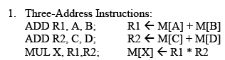
The image above shows a representative sequence for one of the formats. The other sequences are in the images below and they illustrate how the number of instructions and the use of temporaries or registers vary with the instruction format.
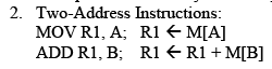
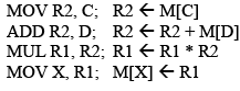
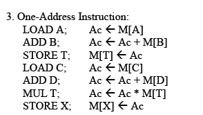
In the sequences above, T denotes a temporary memory location used to store an intermediate result when the instruction format or register availability prevents holding that result in a register. The choice between using registers or memory temporaries affects both instruction count and execution time.
Summary and practical considerations
Instruction formats are a trade-off among instruction word size, program density, simplicity of the CPU control unit and execution speed. Key points to remember:
- The number of address fields in an instruction affects instruction length and the number of instructions needed to implement an algorithm.
- Three-address formats reduce program instruction count but increase instruction word size and decoder complexity.
- Two-address formats are a common compromise in commercial machines.
- One-address formats (accumulator-based) simplify instruction format but typically require more load/store operations.
- Zero-address (stack) machines have very compact instruction formats for many expression evaluations but rely on stack operations and are sensitive to stack performance.
- Choice of instruction set and formats is guided by application needs, typical computations, and hardware design goals (simplicity, speed, code density).
FAQs on Instruction Formats
| 1. What are the different types of instruction formats? |  |
| 2. What is the purpose of an instruction format? | |
| 3. What is the difference between RISC and CISC instruction formats? | |
| 4. How are instruction formats related to CPU performance? | |
| 5. Can instruction formats be changed or updated? | |


 | Explore Courses for Computer Science Engineering (CSE) exam |
 | Get EduRev Notes directly in your Google search |