Computer Configuration


Overview
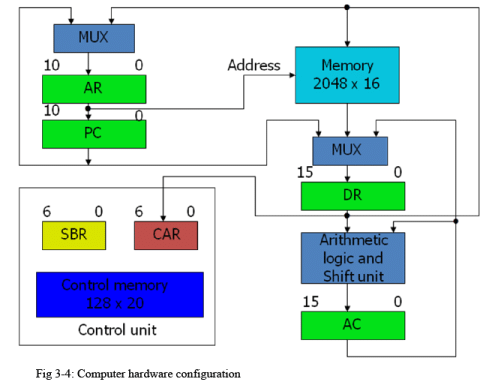
A computer's configuration describes the organisation and interconnection of its hardware components together with the control mechanism that makes them operate as a single system. Once the hardware configuration and a microprogrammed control unit are chosen, the designer must generate the microcode that is stored in the control memory. The process of producing this microcode is called microprogramming.
Principal components in the configuration
- Main memory - stores user programs, instructions and data.
- Control memory - stores the microprogram (microinstructions) that implement the processor's control functions.
- Program Counter (PC) - holds the address of the next machine instruction to be fetched from main memory.
- Address Register (AR) - used to present memory addresses to the main memory.
- Data Register (DR) - holds data read from or to be written into main memory.
- Accumulator (AC) - a primary general-purpose register commonly used for arithmetic and logic operations.
- Control Address Register (CAR) - holds the address of the next microinstruction in control memory.
- Subroutine Register (SBR) - used to save and restore return addresses for microprogram subroutines.
- Register-to-register transfers are implemented by multiplexers and dedicated hardware control signals rather than by a single common bus in some designs; this can reduce contention and simplify control for parallel transfers.
The microprogrammed control unit
The microprogrammed control unit organises the control logic as a sequence of microinstructions stored in control memory. Each microinstruction specifies one or more microoperations (elementary register transfers, ALU operations, memory read/write, etc.) and the method to select the next microinstruction. Control memory may be implemented as ROM (read-only) or as a writable control store (RAM) when the microcode must be modifiable.
What is a microinstruction?
A microinstruction is a control word whose bit fields directly drive hardware control signals and determine sequencing. Typical fields in a microinstruction include:
- Microoperation field - bits that assert specific control signals to perform register transfers, enable ALU operations, read/write memory, etc.
- Next-address field - specifies the address of the next microinstruction when unconditional sequencing is required.
- Branch/condition field - encodes conditional branching based on status flags or conditions.
- Call/return bits - initiate microprogram subroutine call or return using the SBR and CAR.
- Interrupt/priority control bits - optionally used to handle external/internal interrupts within microcode.
Microinstruction formats
Microinstruction formats vary by design. Two common formats are described below.
- Horizontal microinstructions - contain wide control fields where each bit directly controls a single control signal. They are fast and highly parallel but require large control memory and careful organisation.
- Vertical microinstructions - encode control signals in compact fields (encoded operations) and require additional decoding logic. They save control memory at the cost of extra decoding delay and somewhat less parallelism.
Microinstruction sequencing and addressing
Sequencing determines how CAR is updated to point to the next microinstruction. Common sequencing modes are:
- Sequential - CAR is incremented to fetch the next microinstruction address.
- Direct jump - CAR is loaded from the next-address field for an unconditional jump.
- Conditional branch - CAR is loaded from the next-address field when a specified condition (for example, zero flag) is true; otherwise CAR increments.
- Subroutine call - CAR is saved into SBR and CAR is loaded with the subroutine entry address.
- Subroutine return - CAR is loaded from SBR to resume execution after a subroutine.
- Indirect addressing - next-address field points to a memory location that contains the actual microinstruction address (useful for microprogram linking and relocatable microcode).
Microprogramming: generation and example
Microprogramming is the systematic conversion of machine-level instructions into sequences of microinstructions that implement fetch, decode and execute phases. Microcode generation follows these steps:
- Identify the required microoperations for each machine instruction (for example: MAR ← PC, read memory, IR ← MDR, PC ← PC + 1).
- Design the register-transfer microoperations and the control signals needed for each step.
- Arrange microoperations into microinstructions. Determine sequencing and branching for conditional behaviour.
- Encode microinstructions into the chosen microinstruction format (horizontal or vertical).
- Store the microprogram into control memory and test using simulation or hardware verification.
Example: microprogram for a simple LOAD instruction
Consider a machine instruction LOAD AC, M[addr] with the usual fetch-decode-execute cycle. A microprogram may be written as an ordered sequence of microinstructions. Each microinstruction lists the microoperations and the next-address action.
- Fetch 1: AR ← PC; memory read; CAR ← CAR + 1.
- Fetch 2: DR ← M[AR] (from memory); PC ← PC + 1; CAR ← CAR + 1.
- Decode: IR ← DR; AR ← effective address computed from IR; CAR ← address of execute routine for LOAD.
- Execute 1: AR ← address field of IR; memory read; CAR ← CAR + 1.
- Execute 2: DR ← M[AR]; AC ← DR; CAR ← start address for next instruction fetch.
Each line above corresponds to a microinstruction whose fields will assert the appropriate control signals (memory read, register load, ALU operation) and set the CAR for the next microinstruction.
Control memory organisation and implementation
Control memory stores the microprogram. Key considerations:
- Capacity - determined by the number of microinstructions and the width of each microinstruction (for horizontal formats width is large).
- Access time - must match the control timing requirements of the processor; faster access reduces control cycle time.
- Type - ROM for fixed microcode; writable control store (RAM) or EEPROM/Flash when updates are needed.
- Organisation - microinstruction addresses may be organised linearly, or grouped by instruction family for locality and easier debugging.
Advantages and disadvantages of microprogrammed control
- Advantages - easier to design and modify control logic; simpler debugging and verification; uniform method to implement complex instruction sets; allows emulation of different ISAs by changing microcode.
- Disadvantages - typically slower than hardwired control because of the extra memory access and sequencing overhead; control memory increases chip area and cost, especially for wide horizontal microinstructions.
Register transfers and multiplexers
Implementing register-to-register transfers using multiplexers instead of a single common bus is a design choice. Multiplexer-based transfer networks provide:
- Controlled selection of multiple sources to a destination register with reduced bus contention.
- Possibility of simultaneous transfers using dedicated paths, improving parallelism.
- A trade-off of increased wiring and multiplexer hardware against simpler timing and reduced arbitration logic found in shared-bus designs.
Practical design notes
- Keep microoperations atomic and non-overlapping so that each microinstruction produces a deterministic effect in one control cycle.
- Use subroutines to avoid code duplication in the microprogram (SBR and CAR facilitate call/return behaviour).
- When using vertical microinstructions, document the decoder mapping carefully; changes in encoding require updates to decoding logic and verification.
- Consider microprogram debugging features such as single-step execution, trace buffers and breakpoint microinstructions when implementing a writable control store.
Applications and conclusions
Microprogramming is widely used in processor control units where flexibility, ease of implementation and maintainability are important. It is particularly useful for complex instruction set processors and educational or prototyping platforms. Designers must balance performance (favoring hardwired control or very wide horizontal microinstructions) and flexibility (favoring microprogramming with writable control store).
If further detail is required on microinstruction encoding, microprogram verification or an illustrated block diagram walkthrough using the shown figure, such expansions can be provided with worked examples of encoding bit-fields and stepwise microinstruction execution traces.
FAQs on Computer Configuration
| 1. What is computer configuration? |  |
| 2. How can I check my computer's configuration? | |
| 3. What factors should I consider when choosing a computer configuration? | |
| 4. Can I upgrade the configuration of my computer? | |
| 5. What is the importance of a good computer configuration for gaming? | |


 | Explore Courses for Computer Science Engineering (CSE) exam |
 | Get EduRev Notes directly in your Google search |