Computer Science Engineering (CSE) Exam > Computer Science Engineering (CSE) Notes > Computer Architecture & Organisation (CAO) > Microinstruction Format
Microinstruction Format | Computer Architecture & Organisation (CAO) - Computer Science Engineering (CSE) PDF Download

Microinstruction Format
Computer Instruction Format
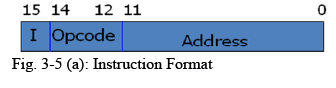
- The computer instruction format is depicted in Fig. 3-5(a).
- It consists of three fields:
- A 1-bit field for indirect addressing symbolized by I
- A 4-bit operation code (opcode)
- An 11-bit address field
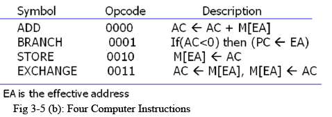
- Fig. 3-5(b) lists four of the 16 possible memory-reference instructions.
Microinstruction Format
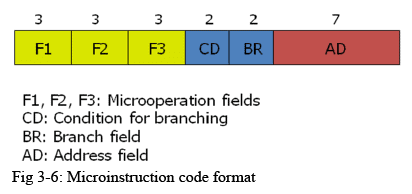
- The microinstruction format for the control memory is shown in Fig. 3-6.
- The 20 bits of the microinstruction are divided into four functional parts.
- The three fields F1, F2, and F3 specify microoperations for the computer.
- The CD field selects status bit conditions.
- The BR field specifies the type of branch.
- The AD field contains a branch address.
Microoperations
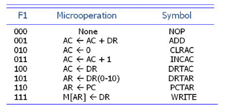
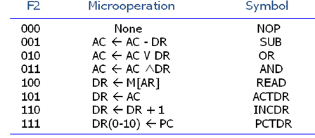
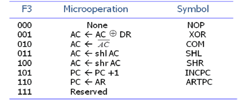
- The three bits in each field are encoded to specify seven distinct microoperations as listed in Table 3-1.
- No more than three microoperations can be chosen for a microinstruction, one from each field.
- If fewer than three microoperations are used, one or more of the fields will use the binary code 000 for no operation.
- It is important to realize that two or more conflicting microoperations cannot be specified simultaneously. e.g. 010 001 000
- Each microoperation in Table 3-1 is defined with a register transfer statement and is assigned a symbol for use in a symbolic microprogram.
Question for Microinstruction FormatTry yourself: What are the three fields in the microinstruction format for the control memory?View Solution
Condition and Branch Field
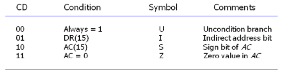
- The CD field consists of two bits which are encoded to specify four status bit conditions as listed in Table 3-1.
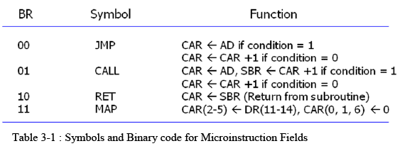
- The BR field consists of two bits. It is used, in conjunction with the address field AD, to choose the address of the next microinstruction.
- The jump and call operations depend on the value of the CD field.
- The two operations are identical except that a call microinstruction stores the return address in the subroutine register SBR.
- Note that the last two conditions in the BR field are independent of the values in the CD and AD fields.
The document Microinstruction Format | Computer Architecture & Organisation (CAO) - Computer Science Engineering (CSE) is a part of the Computer Science Engineering (CSE) Course Computer Architecture & Organisation (CAO).
All you need of Computer Science Engineering (CSE) at this link: Computer Science Engineering (CSE)
|
20 videos|105 docs|48 tests
|
FAQs on Microinstruction Format - Computer Architecture & Organisation (CAO) - Computer Science Engineering (CSE)
| 1. What is the microinstruction format? |  |
Ans. Microinstruction format refers to the structure or layout of a microinstruction that is used to direct the operation of a microprocessor. It includes the various fields or components that make up a microinstruction, such as the operation code, address field, control field, and others.
| 2. What is the purpose of a microinstruction format? | |
Ans. The purpose of a microinstruction format is to provide a standardized way of encoding machine-level instructions that can be executed by a microprocessor. By following a specific format, microinstructions can be easily decoded and executed by the processor, allowing it to perform complex tasks and operations.
| 3. What are some common components of a microinstruction format? | |
Ans. Some common components of a microinstruction format include the operation code (opcode), which specifies the operation to be performed, the address field, which specifies the memory location or register to be accessed, the control field, which contains control signals that direct the processor's operation, and the microprogram counter (MPC), which specifies the next microinstruction to be executed.
| 4. How is a microinstruction format different from an instruction set architecture (ISA)? | |
Ans. A microinstruction format is a low-level representation of machine-level instructions that are executed by a microprocessor, while an ISA is a higher-level abstraction that defines the set of instructions that a processor can execute. The microinstruction format is used by the processor's control unit to execute individual instructions, while the ISA is used by software developers to write programs that can be executed on the processor.
| 5. What is the role of microcode in a microinstruction format? | |
Ans. Microcode is the low-level programming language that is used to write microinstructions for a microprocessor. The microinstruction format specifies the structure and layout of these microinstructions, while the microcode provides the specific instructions that the processor will execute. Microcode is stored in the processor's control unit and is used to implement the instructions specified by the ISA.
About this Document

30.3K Views

4.77/5
Rating

Sep 28, 2025
Last updated
Related Exams
Document Description: Microinstruction Format for Computer Science Engineering (CSE) 2025 is part of Computer Architecture & Organisation (CAO) preparation.
The notes and questions for Microinstruction Format have been prepared according to the Computer Science Engineering (CSE) exam syllabus. Information about Microinstruction Format covers topics
like and Microinstruction Format Example, for Computer Science Engineering (CSE) 2025 Exam. Find important definitions, questions, notes, meanings, examples, exercises and tests below for Microinstruction Format.
Introduction of Microinstruction Format in English is available as part of our Computer Architecture & Organisation (CAO)
for Computer Science Engineering (CSE) & Microinstruction Format in Hindi for Computer Architecture & Organisation (CAO) course.
Download more important topics related with notes, lectures and mock test series for Computer Science Engineering (CSE)
Exam by signing up for free. Computer Science Engineering (CSE): Microinstruction Format | Computer Architecture & Organisation (CAO) - Computer Science Engineering (CSE)
Description
Full syllabus notes, lecture & questions for Microinstruction Format | Computer Architecture & Organisation (CAO) - Computer Science Engineering (CSE) - Computer Science Engineering (CSE) | Plus excerises question with solution to help you revise complete syllabus for Computer Architecture & Organisation (CAO) | Best notes, free PDF download
Information about Microinstruction Format
In this doc you can find the meaning of Microinstruction Format defined & explained in the simplest way possible. Besides explaining types of
Microinstruction Format theory, EduRev gives you an ample number of questions to practice Microinstruction Format tests, examples and also practice Computer Science Engineering (CSE)
tests
|
20 videos|105 docs|48 tests
|
Download as PDF

|
Explore Courses for Computer Science Engineering (CSE) exam
|

|
Related Searches
video lectures
,Important questions
,practice quizzes
,shortcuts and tricks
,past year papers
,Free
,Semester Notes
,Objective type Questions
,Extra Questions
,Sample Paper
,study material
,Viva Questions
,ppt
,mock tests for examination
,Microinstruction Format | Computer Architecture & Organisation (CAO) - Computer Science Engineering (CSE)
,Microinstruction Format | Computer Architecture & Organisation (CAO) - Computer Science Engineering (CSE)
,Summary
,Microinstruction Format | Computer Architecture & Organisation (CAO) - Computer Science Engineering (CSE)
,Previous Year Questions with Solutions
,Exam
,MCQs
;




Additional Information about Microinstruction Format for Computer Science Engineering (CSE) Preparation
Microinstruction Format Free PDF Download
The Microinstruction Format is an invaluable resource that delves deep into the core of the Computer Science Engineering (CSE) exam.
These study notes are curated by experts and cover all the essential topics and concepts, making your preparation more efficient and effective.
With the help of these notes, you can grasp complex subjects quickly, revise important points easily,
and reinforce your understanding of key concepts. The study notes are presented in a concise and easy-to-understand manner,
allowing you to optimize your learning process. Whether you're looking for best-recommended books, sample papers, study material,
or toppers' notes, this PDF has got you covered. Download the Microinstruction Format now and kickstart your journey towards success in the Computer Science Engineering (CSE) exam.
Importance of Microinstruction Format
The importance of Microinstruction Format cannot be overstated, especially for Computer Science Engineering (CSE) aspirants.
This document holds the key to success in the Computer Science Engineering (CSE) exam.
It offers a detailed understanding of the concept, providing invaluable insights into the topic.
By knowing the concepts well in advance, students can plan their preparation effectively.
Utilize this indispensable guide for a well-rounded preparation and achieve your desired results.
Microinstruction Format Notes
Microinstruction Format Notes offer in-depth insights into the specific topic to help you master it with ease.
This comprehensive document covers all aspects related to Microinstruction Format.
It includes detailed information about the exam syllabus, recommended books, and study materials for a well-rounded preparation.
Practice papers and question papers enable you to assess your progress effectively.
Additionally, the paper analysis provides valuable tips for tackling the exam strategically.
Access to Toppers' notes gives you an edge in understanding complex concepts.
Whether you're a beginner or aiming for advanced proficiency, Microinstruction Format Notes on EduRev are your ultimate resource for success.
Microinstruction Format Computer Science Engineering (CSE) Questions
The "Microinstruction Format Computer Science Engineering (CSE) Questions" guide is a valuable resource for all aspiring students preparing for the
Computer Science Engineering (CSE) exam. It focuses on providing a wide range of practice questions to help students gauge
their understanding of the exam topics. These questions cover the entire syllabus, ensuring comprehensive preparation.
The guide includes previous years' question papers for students to familiarize themselves with the exam's format and difficulty level.
Additionally, it offers subject-specific question banks, allowing students to focus on weak areas and improve their performance.
Study Microinstruction Format on the App
Students of Computer Science Engineering (CSE) can study Microinstruction Format alongwith tests & analysis from the EduRev app,
which will help them while preparing for their exam. Apart from the Microinstruction Format,
students can also utilize the EduRev App for other study materials such as previous year question papers, syllabus, important questions, etc.
The EduRev App will make your learning easier as you can access it from anywhere you want.
The content of Microinstruction Format is prepared as per the latest Computer Science Engineering (CSE) syllabus.
|
© EduRev
|
Education Revolution
|


|




Signup on EduRev and stay on top of your study goals
10M+ students crushing their study goals daily