Instruction Pipelining

Instruction Pipelining
As processor technology advances, overall system performance is improved by several organisational and architectural techniques such as faster logic, multiple registers instead of a single accumulator, and the use of cache memory. Another important organisational technique is instruction pipelining, in which different steps of instruction processing are overlapped so that a new instruction can be accepted at the beginning of the pipeline before the previous instruction has completed at the end.
- The basic idea of pipelining is similar to an assembly line: split instruction execution into stages, place registers or buffers between stages and feed a sequence of instructions into the pipeline. Each stage performs part of the work; successive instructions occupy successive stages simultaneously.
- A simple two-stage pipeline separates instruction processing into a fetch stage and an execute stage. The fetch stage reads an instruction from memory into a buffer; when the execute stage becomes free, the buffered instruction is passed on for execution. While the execute stage works, the fetch stage obtains the next instruction. This overlap is often called instruction prefetch or fetch overlap.
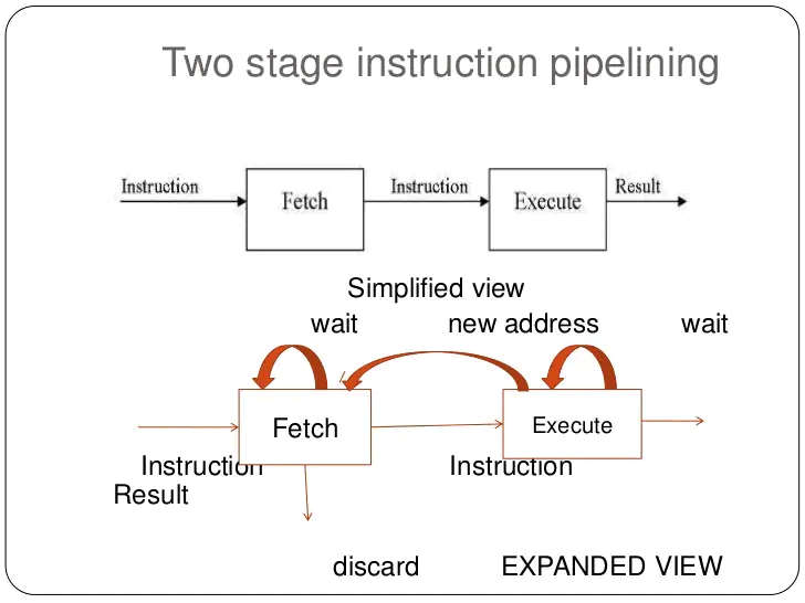
- If the fetch and execute stages took the same duration, a two-stage pipeline could double instruction throughput. In practice, stage durations differ and simple two-stage pipelines rarely produce an exact factor-of-two speedup.
- Three principal issues prevent ideal speedup in the two-stage pipeline:
- Stage imbalance: The execute stage usually takes longer than the fetch stage, so the fetch stage cannot always keep the execute stage supplied.
- Control hazards (branches): A conditional branch makes the address of the next instruction unknown until the branch is resolved; the fetch stage must stall until the execute stage supplies the correct next-PC.
- Fetched-but-invalid instructions: When a branch is taken, instructions fetched following the branch must be discarded and the correct target fetched, causing wasted cycles.
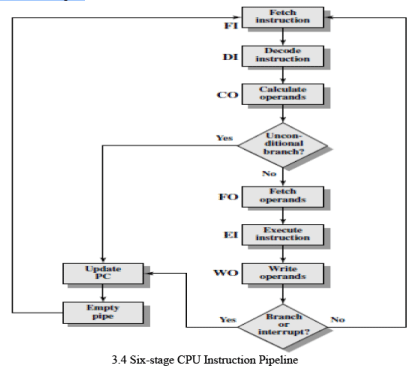
To improve the overlap further, designers decompose instruction processing into more stages. A common six-stage decomposition is:
- Fetch Instruction (FI): Read the next expected instruction into an instruction buffer.
- Decode Instruction (DI): Decode the opcode and determine addressing modes and operand specifiers.
- Calculate Operands (CO): Compute effective addresses for source operands (displacement, register indirect, indexed, etc.).
- Fetch Operands (FO): Read source operands from register file or memory.
- Execute Instruction (EI): Perform the ALU or other operation and compute results.
- Write Operand (WO): Write the result back to the destination register or memory.
Splitting work into more stages increases instruction concurrency: several instructions can be in flight simultaneously, each in a different stage of processing.
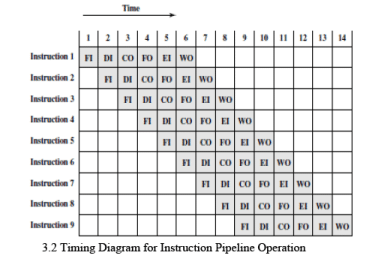
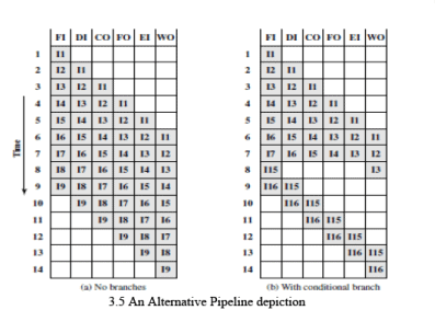
- A six-stage pipeline can substantially reduce total execution time. For example, if each non-pipelined instruction requires 6 time units, nine instructions would take 54 time units without pipelining. With a six-stage pipeline, the same nine instructions complete in 14 cycle times (see example figure).
- Stages that access memory (FO and WO) are often slower than register stages; stage-duration imbalance introduces stalls because the pipeline cycle time must accommodate the slowest stage.
- Conditional branches and unexpected interrupts can invalidate several prefetched instructions and require pipeline control to discard or re-fetch instructions; this causes performance penalties.
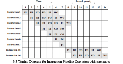
Consider an example where, in a sequence of instructions, instruction 3 is a conditional branch to instruction 15. The pipeline may continue fetching subsequent sequential instructions (I4, I5, ...) until the branch is resolved. If the branch is not taken, these fetches are useful and no penalty occurs. If the branch is taken, the prefetched instructions must be flushed and the pipeline redirected to the target; this produces a delay while the pipeline refills with correct instructions.
- The pipeline state can be visualised with time shown vertically (each row is the pipeline state during a cycle). When a branch is resolved late in the sequence, several instructions already in the pipeline must be removed, leaving the pipeline partially empty until new instructions are fetched and decoded.
- Interrupts are an analogous unpredictable event: the pipeline must be drained or a precise state must be established before servicing the interrupt, which also causes a performance penalty.
Pipelining Performance
- The pipeline cycle time t is the time required to advance the pipeline by one stage (i.e., the time between successive pipeline register updates). Each pipeline stage must complete its portion of the work within one cycle time.
- The cycle time t is determined by the slowest pipeline stage plus the overhead of the pipeline register (latch) between stages:
t = max(ti) + d = tm + d
where
- ti = delay of the circuitry in the i-th stage
- tm = maximum stage delay among all stages
- d = latch (or register) delay used to transfer signals between stages
- k = number of pipeline stages
- Assuming there are no branches or stalls, the total time Tk,n to execute n instructions on a k-stage pipeline is:
Tk,n = [k + (n - 1)] · t
k cycles are required to fill the pipeline for the first instruction, and each of the remaining n - 1 instructions completes in one additional cycle.
- For an equivalent non-pipelined processor that implements the same k functional stages sequentially, each instruction takes k·t time units (if we assume each original stage time equals t). The total time for n instructions is:
Tnon-pipe,n = n · k · t
- The speedup sk achieved by the k-stage pipeline (ignoring overheads from hazards and control) is:
sk = Tnon-pipe,n / Tk,n = (n · k · t) / ([k + (n - 1)] · t) = (n · k) / (k + n - 1)
As n becomes large, sk approaches k, the number of pipeline stages, which is the theoretical maximum speedup.
- Example: For k = 6 stages and n = 9 instructions,
Tk,n = (6 + 9 - 1) · t = 14 · t
Tnon-pipe,n = 9 · 6 · t = 54 · t
s6 = 54 / 14 ≈ 3.857
This illustrates the practical speedup for a short instruction sequence; the speedup improves further as n grows.
Pipeline Hazards and Remedies
- Structural hazards: Occur when two stages require the same hardware resource simultaneously (for example, a single memory used for both instruction fetch and data access). Remedies include duplicating resources (separate instruction and data caches), careful pipeline design and resource arbitration.
- Data hazards: Occur when an instruction depends on the result of a prior instruction that has not yet completed its write-back. Types include RAW (read after write), WAR (write after read) and WAW (write after write). Common remedies:
- Pipeline stalls (bubbles): Delay dependent instruction until data is available.
- Operand forwarding (bypassing): Forward result from a later stage (for example, from ALU output) back to an earlier stage to avoid waiting for write-back.
- Compiler scheduling: Reorder instructions at compile time to reduce hazards.
- Control hazards (branches): Occur when the next instruction address depends on the outcome of a branch. Remedies include:
- Stalling until branch resolves: Simple but costly.
- Branch prediction: Predict whether the branch will be taken and continue fetching along the predicted path; on misprediction, flush the incorrect instructions and fetch the correct ones.
- Delayed branching: The compiler arranges useful instructions in the delay slots immediately following a branch, so a few cycles are not wasted regardless of branch outcome.
- Speculative execution: Execute both paths or speculatively execute along a predicted path, committing results only if prediction is correct.
- Interrupts: Require saving a precise state; pipelines must be drained or hardware must support precise interrupt handling so that the register state corresponds to an exact instruction boundary.
Design Trade-offs and Practical Considerations
- Stage overhead and latching delay: Every pipeline register (latch or flip-flop) adds delay d. If d is large relative to stage logic delays, increasing pipeline depth can reduce or eliminate benefit. Designers must balance the logic per stage with latch overhead.
- Complexity of control logic: As the number of stages increases, control for hazard detection, forwarding, stall insertion and out-of-order behaviour grows more complex. Excessive control complexity may offset performance gains.
- Pipeline depth: Deeper pipelines allow higher clock frequencies (smaller t) but increase branch penalty (more instructions to flush on misprediction) and may complicate forwarding and exception handling.
- Instruction mix and locality: Real-world speedup depends on the program behaviour: frequency of branches, data dependencies, memory stalls, and cache effectiveness determine achieved performance.
Summary
Instruction pipelining is an effective technique to increase instruction throughput by overlapping the processing of multiple instructions. The theoretical speedup approaches the number of pipeline stages for long instruction sequences, but several practical factors reduce the realised speedup: stage imbalance, latch overhead, structural, data and control hazards, branch penalties and increased control logic complexity. Techniques such as forwarding, stall insertion, branch prediction, speculative execution and compiler scheduling are used to mitigate these hazards. Pipeline design therefore involves trade-offs among depth, clock rate, hardware complexity and the expected instruction mix.
FAQs on Instruction Pipelining
| 1. What is instruction pipelining in computer science engineering? |  |
| 2. How does instruction pipelining improve performance? | |
| 3. What are the stages involved in instruction pipelining? | |
| 4. What are the challenges in implementing instruction pipelining? | |
| 5. Are there any limitations to instruction pipelining? | |


 | Explore Courses for Computer Science Engineering (CSE) exam |
 | Get EduRev Notes directly in your Google search |