Bipolar Transistor Configurations | Analog and Digital Electronics - Electrical Engineering (EE) PDF Download

Bipolar Transistor Configurations

As the Bipolar Transistor is a three terminal device, there are basically three possible ways to connect it within an electronic circuit with one terminal being common to both the input and output. Each method of connection responds differently to its input signal within a circuit as the static characteristics of the transistor vary with each circuit arrangement.

  • Common Base Configuration - has Voltage Gain but no Current Gain.
  • Common Emitter Configuration - has both Current and Voltage Gain.
  • Common Collector Configuration - has Current Gain but no Voltage Gain

COMMON-BASE CONFIGURATION

Common-base terminology is derived from the fact that the : base is common to both input and output of the configuration. Base is usually the terminal closest to or at ground potential. Majority carriers can cross the reverse-biased junction because the injected majority carriers will appear as minority carriers in the n-type material. All current directions will refer to conventional (hole) flow and the arrows in all electronic symbols have a direction defined by this convention.

Note that the applied biasing (voltage sources) are such so as to establish current in the direction indicated for each branch.
 

                    Bipolar Transistor Configurations | Analog and Digital Electronics - Electrical Engineering (EE)

To describe the behavior of common-base amplifiers requires two sets of characteristics:

  1. Input or driving point characteristics.
  2. Output or collector characteristics

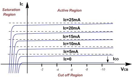
The output characteristics has 3 basic regions:

  • Active region –defined by the biasing arrangements.
  • Cutoff region – region where the collector current is 0A.
  • Saturation region- region of the characteristics to the left of VCB = 0V.

                           Bipolar Transistor Configurations | Analog and Digital Electronics - Electrical Engineering (EE)  


                 Bipolar Transistor Configurations | Analog and Digital Electronics - Electrical Engineering (EE)


                              Bipolar Transistor Configurations | Analog and Digital Electronics - Electrical Engineering (EE)


The curves (output characteristics) clearly indicate that a first approximation to the relationship between IE and IC in the active region is given by

IC ≈IE

Once a transistor is in the ‘on’ state, the base-emitter voltage will be assumed to be VBE = 0.7V

                                   Bipolar Transistor Configurations | Analog and Digital Electronics - Electrical Engineering (EE)

In the dc mode, the level of I and IE due to the majority charge carriers are related by a quantity called alpha, a= αdc

IC = aIE + ICBO

It can then be summarized to IC = aIE (ignore ICBO due to small value)

For ac situations where the point of operation moves on the characteristics curve, an ac alpha defined by αac.

Alpha is a common base current gain factor that shows the efficiency by calculating the percentage of current flow from emitter to collector. The value of a is typical from 0.9 ~ 0.998.

Biasing:Proper biasing CB configuration in active region by  approximation IC ≈ IE (IB ≈ 0 uA)

                        Bipolar Transistor Configurations | Analog and Digital Electronics - Electrical Engineering (EE)

The document Bipolar Transistor Configurations | Analog and Digital Electronics - Electrical Engineering (EE) is a part of the Electrical Engineering (EE) Course Analog and Digital Electronics.
All you need of Electrical Engineering (EE) at this link: Electrical Engineering (EE)
137 videos|143 docs|71 tests

Top Courses for Electrical Engineering (EE)

FAQs on Bipolar Transistor Configurations - Analog and Digital Electronics - Electrical Engineering (EE)

1. What are the different bipolar transistor configurations?
Ans. The three main bipolar transistor configurations are the common emitter, common base, and common collector configurations. In the common emitter configuration, the emitter is common to both the input and output circuits. In the common base configuration, the base is common to both the input and output circuits. In the common collector configuration, the collector is common to both the input and output circuits.
2. What is the advantage of the common emitter configuration?
Ans. The common emitter configuration offers a high voltage gain, making it suitable for applications such as amplifiers. It also provides a phase inversion between the input and output signals, which can be useful in certain applications.
3. How does the common base configuration differ from the common emitter configuration?
Ans. In the common base configuration, the input signal is applied to the emitter terminal, while the output is taken from the collector terminal. This configuration offers a low input impedance and a voltage gain less than 1. It is commonly used in applications requiring current amplification and impedance matching.
4. What is the purpose of the biasing circuit in a bipolar transistor configuration?
Ans. The biasing circuit in a bipolar transistor configuration is used to establish the operating point or quiescent point of the transistor. It ensures that the transistor operates within its linear region and provides the required DC biasing conditions for proper amplification.
5. How can the common collector configuration be utilized in practical applications?
Ans. The common collector configuration, also known as the emitter follower, is often used as a buffer or impedance matching circuit. It has a voltage gain slightly less than 1 but offers a high input impedance and a low output impedance. This configuration is commonly employed to isolate the preceding stage from the following stage in a multi-stage amplifier.
137 videos|143 docs|71 tests
Download as PDF
Explore Courses for Electrical Engineering (EE) exam

Top Courses for Electrical Engineering (EE)

Signup for Free!
Signup to see your scores go up within 7 days! Learn & Practice with 1000+ FREE Notes, Videos & Tests.
10M+ students study on EduRev
Related Searches

Sample Paper

,

shortcuts and tricks

,

Bipolar Transistor Configurations | Analog and Digital Electronics - Electrical Engineering (EE)

,

Important questions

,

Free

,

Semester Notes

,

practice quizzes

,

pdf

,

ppt

,

Objective type Questions

,

Bipolar Transistor Configurations | Analog and Digital Electronics - Electrical Engineering (EE)

,

mock tests for examination

,

Bipolar Transistor Configurations | Analog and Digital Electronics - Electrical Engineering (EE)

,

Summary

,

study material

,

past year papers

,

MCQs

,

video lectures

,

Exam

,

Viva Questions

,

Extra Questions

,

Previous Year Questions with Solutions

;