Electrical Engineering (EE) Exam  >  Electrical Engineering (EE) Tests  >  Test: Power Systems- 2 - Electrical Engineering (EE) MCQ

Test: Power Systems- 2 - Electrical Engineering (EE) MCQ


Test Description

20 Questions MCQ Test - Test: Power Systems- 2

Test: Power Systems- 2 for Electrical Engineering (EE) 2024 is part of Electrical Engineering (EE) preparation. The Test: Power Systems- 2 questions and answers have been prepared according to the Electrical Engineering (EE) exam syllabus.The Test: Power Systems- 2 MCQs are made for Electrical Engineering (EE) 2024 Exam. Find important definitions, questions, notes, meanings, examples, exercises, MCQs and online tests for Test: Power Systems- 2 below.
Solutions of Test: Power Systems- 2 questions in English are available as part of our course for Electrical Engineering (EE) & Test: Power Systems- 2 solutions in Hindi for Electrical Engineering (EE) course. Download more important topics, notes, lectures and mock test series for Electrical Engineering (EE) Exam by signing up for free. Attempt Test: Power Systems- 2 | 20 questions in 12 minutes | Mock test for Electrical Engineering (EE) preparation | Free important questions MCQ to study for Electrical Engineering (EE) Exam | Download free PDF with solutions
Test: Power Systems- 2 - Question 1

In transmission lines, the effective resistance of a conductor is increased by

Detailed Solution for Test: Power Systems- 2 - Question 1

Skin effect is the tendency of an alternating electric current to become distributed within a conductor such that the current density is largest near the surface of the conductor and decreases with greater depths in the conductor.

The electric current flows mainly at the skin of the conductor, between the outer surface and a level called the skin depth. The skin effect causes the effective resistance of the conductor to increase at higher frequencies where the skin depth is smaller, thus reducing the effective cross-section of the conductor.

The alternating flux in a conductor is caused by the current of the other nearby conductor. This flux produces a circulating current or eddy current in the conductor which results an apparent increase in the resistance of the wire. Thus, more power losses in the windings. This phenomenon is called proximity effect.

Test: Power Systems- 2 - Question 2

The main consideration for operating transmission line at high voltage is

Detailed Solution for Test: Power Systems- 2 - Question 2

The main considerations for operating transmission line at high voltage are:

1) To increase efficiency only

2) To reduce power loss only

3) To increase power transmission capability

1 Crore+ students have signed up on EduRev. Have you? Download the App
Test: Power Systems- 2 - Question 3

Consider the following statements

High voltage is used in long distance power transmission in order to:

1) Reduce the time of transmission

2) Reduce the transmission losses

3) Make the system reliable

Out of these, the correct statements are?

Detailed Solution for Test: Power Systems- 2 - Question 3

High voltage is used in long distance power transmission in order to

1) Reduce the time of transmission

2) Reduce the transmission losses

3) Make the system reliable

Test: Power Systems- 2 - Question 4

Skin effect results

Detailed Solution for Test: Power Systems- 2 - Question 4

Skin effect is the tendency of an alternating electric current to become distributed within a conductor such that the current density is largest near the surface of the conductor and decreases with greater depths in the conductor.

The electric current flows mainly at the skin of the conductor, between the outer surface and a level called the skin depth. The skin effect causes the effective resistance of the conductor to increase at higher frequencies where the skin depth is smaller, thus reducing the effective cross-section of the conductor.

Hence resistance in AC is greater than resistance in DC

Test: Power Systems- 2 - Question 5

In the analysis of short transmission lines, which of the following is neglected?

Detailed Solution for Test: Power Systems- 2 - Question 5

The transmission lines which have length less than 50 km are generally referred as short transmission lines.

For short length, the shunt capacitance of this type of line is neglected and other parameters like electrical resistance and inductance are lumped

Test: Power Systems- 2 - Question 6

Which of the following used to make bus bars and transmission line conductors?

Detailed Solution for Test: Power Systems- 2 - Question 6

Aluminium is used for a whole range of busbar applications and to make transmission line conductors due to its light weight and durability.

Test: Power Systems- 2 - Question 7

Which of the following is not a type of insulator used in overhead transmission line?

Detailed Solution for Test: Power Systems- 2 - Question 7

Different types of insulators used in overhead transmission line are:

1) Pin type

2) Suspension type

3) Strain type

4) Stay insulator

5) Shackle insulator

Rivet type is not a type of insulator used in overhead transmission line

Test: Power Systems- 2 - Question 8

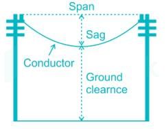
Sag of conductor’s between two poles can be determined by:

Detailed Solution for Test: Power Systems- 2 - Question 8

Sag is defined as the difference in level between points of supports and the lowest point on the conductor.

Sag of conductor’s between two poles can be determined by

Where, S is the sag of conductors

W is the weight per unit length of the conductor

L is the length of span

T is the tension in the conductor

Test: Power Systems- 2 - Question 9

Cables in power transmission line are provided with inter sheaths to:

Detailed Solution for Test: Power Systems- 2 - Question 9

Cables in power transmission line are provided with inter sheaths to provide proper distribution of stress.

Test: Power Systems- 2 - Question 10

When feeder ring distributes energy from two or more than two production plants, then this distribution system is known as:

Detailed Solution for Test: Power Systems- 2 - Question 10

Radial Distribution System: This system is used only when substation is located at the center of the consumers. In this system, different feeders radiate from a substation and feed the distributors at one end. Thus, the main characteristic of a radial distribution system is that the power flow is in only one direction. It is the simplest system and has the lowest initial cost but it is not highly reliable.

A major drawback of a radial distribution system is, a fault in the feeder will result in supply failure to associated consumers as there won't be any alternative feeder to feed distributors.

Ring main system: In this system, each distribution transformer is fed with two feeders but in different paths. The feeders in this system form a loop which starts from the substation bus-bars, runs through the load area feeding distribution transformers and returns to the substation bus-bars.

Ring main distribution system is the most preferred due to its following advantages:

1) There are fewer voltage fluctuations at consumer's terminal.

2) The system is very reliable as each distribution transformer is fed with two feeders. That means, in the event of a fault in any section of the feeder, the continuity of the supply is ensured from the alternative path.

Interconnected distribution system: When a ring main feeder is energized by two or more substations, it is called as an interconnected distribution system. This system ensures reliability in an event of transmission failure. Also, any area fed from one generating station during peak load hours can be fed from the other generating station or substation for meeting power requirements from increased load.

Test: Power Systems- 2 - Question 11

Power factor can be improved by:

Detailed Solution for Test: Power Systems- 2 - Question 11

Power factor can be improved by

1) Synchronous machine

2) STATCOM

3) Static VAR Compensator

Test: Power Systems- 2 - Question 12

A fault involving all the three phase of a power system is known as

Detailed Solution for Test: Power Systems- 2 - Question 12

In the following two faults, fault occurs in all the three phases of power system.

1) LLL fault (Line-Line-Line fault)

2) LLLG fault (Line-Line-Line-Ground fault)

These two faults are symmetrical faults.

Test: Power Systems- 2 - Question 13

What are Oil switches used for?

Detailed Solution for Test: Power Systems- 2 - Question 13

Oil switches: As the name implies, the contacts of switches are opened under oil. Usually transformer oil is used whose purpose is to cool and quench the arc formed on account of opening the contacts. These switches are used for circuits of high voltage and large current carrying capacities.

Air break switches are generally used outdoors for circuits of medium capacity such as lines supplying an industrial load from a main transmission line or feeder

Test: Power Systems- 2 - Question 14

The least expensive protection for over-current in low voltage system is:

Detailed Solution for Test: Power Systems- 2 - Question 14

Rewirable fuses are most commonly used in housing wiring and small current circuits. It is also known as a kit-kat fuse. It has a porcelain base which is carrying the fixed contact through which the live wires are connected. The fuse carrier is the independent part which is easily removed or stuck in the base.

The fuse element is made of lead, tin, copper or alloy of tin-lead. The current required for melting the fusing element is twice the value of normal operating current.

The rewirable fuse has the advantages of replacement of fuse element without any risk. The cost of the replacement is also very less.

Test: Power Systems- 2 - Question 15

During current chopping the current actually breaks..

Detailed Solution for Test: Power Systems- 2 - Question 15

Current chopping in circuit breaker is defined as a phenomenon in which current is forcibly interrupted before the natural current zero. Current Chopping is mainly observed in vacuum circuit breaker and air blast circuit breaker. There is no such phenomena in oil circuit breaker. Current chopping is predominant while switching shunt reactor or unloaded transformer.

Generally the arc extinction in a circuit breaker take place at natural current zero. But this is true if the capacity of the breaker to extinguish the arc varies with the level of fault current. This means that, the arc extinction capability of breaker will always ensure that arc extinction is taking place at natural current zero.

Test: Power Systems- 2 - Question 16

In terms of relays, IDMT relays stands for

Detailed Solution for Test: Power Systems- 2 - Question 16

IDMT relay stands for Inverse definite minimum time lag relay. It is protection relay. It is used on transmission lines to see that the line current doesn't exceed safe values and if it does, triggers the circuit breaker. It decreases the tripping time for a higher fault.

Test: Power Systems- 2 - Question 17

Differential protection for feeders consist of:

Detailed Solution for Test: Power Systems- 2 - Question 17

Differential protection for feeders consist of

1) Voltage balance differential relay

2) Current balance differential relay

Test: Power Systems- 2 - Question 18

Power plant having maximum demand more than installed capacity will have utilization factor:

Detailed Solution for Test: Power Systems- 2 - Question 18

If maximum demand is more than installed capacity, station output will be more than the installed plant capacity.

Hence utilization factor will be more than 100%

Test: Power Systems- 2 - Question 19

Load curve helps in deciding:

Detailed Solution for Test: Power Systems- 2 - Question 19

A load curve is a plot of the load demand with respect to the time in the chronological order

From the load curve, the following information can be obtained

1) The variation of load on the power system during different hours of the day

2) Number of units generated

3) The highest point in the curve indicates the maximum demand on the power station

4) The area of the curve divided by time gives the average load on the power station

By observing the above information, it helps in deciding

1. The total installed capacity of the plant

2. The size of the generating units

3. The operating schedule of the generating units

Test: Power Systems- 2 - Question 20

The average motor load of a consumer is 250 kW at a power factor 0.85 lag. The consumer is charged electricity at the tariff of Rs.50/kVA of maximum demand plus 10 paise per unit consumed. Determine the consumer’s annual bill for a load factor of 70%

Detailed Solution for Test: Power Systems- 2 - Question 20

Consumer motor load = 250 kW

Maximum demand = 250/0.85 = 294.11

Unit consumed per year = maximum demand × load factor × hours in a year

= 250 × 0.7 × 8760 = 1533000 kWh

Annual bill = Max demand charges + energy charges

= (294.11 × 50) + (1533000 × 0.1) = Rs. 168005.5

Information about Test: Power Systems- 2 Page
In this test you can find the Exam questions for Test: Power Systems- 2 solved & explained in the simplest way possible. Besides giving Questions and answers for Test: Power Systems- 2, EduRev gives you an ample number of Online tests for practice

Top Courses for Electrical Engineering (EE)

Download as PDF

Top Courses for Electrical Engineering (EE)