Electrical Engineering (EE) Exam  >  Electrical Engineering (EE) Tests  >  Test: Electrical Circuits- 2 - Electrical Engineering (EE) MCQ

Test: Electrical Circuits- 2 - Electrical Engineering (EE) MCQ


Test Description

20 Questions MCQ Test - Test: Electrical Circuits- 2

Test: Electrical Circuits- 2 for Electrical Engineering (EE) 2024 is part of Electrical Engineering (EE) preparation. The Test: Electrical Circuits- 2 questions and answers have been prepared according to the Electrical Engineering (EE) exam syllabus.The Test: Electrical Circuits- 2 MCQs are made for Electrical Engineering (EE) 2024 Exam. Find important definitions, questions, notes, meanings, examples, exercises, MCQs and online tests for Test: Electrical Circuits- 2 below.
Solutions of Test: Electrical Circuits- 2 questions in English are available as part of our course for Electrical Engineering (EE) & Test: Electrical Circuits- 2 solutions in Hindi for Electrical Engineering (EE) course. Download more important topics, notes, lectures and mock test series for Electrical Engineering (EE) Exam by signing up for free. Attempt Test: Electrical Circuits- 2 | 20 questions in 12 minutes | Mock test for Electrical Engineering (EE) preparation | Free important questions MCQ to study for Electrical Engineering (EE) Exam | Download free PDF with solutions
Test: Electrical Circuits- 2 - Question 1

If the energy is supplied form a source, whose resistance is 1 Ohm, to a load of 100 Ohms the source will be

Detailed Solution for Test: Electrical Circuits- 2 - Question 1

The internal resistance of an ideal voltage source should be zero and practically it is very low.

Given that, source resistance is 1 ohm

Hence the source will be a voltage source

Test: Electrical Circuits- 2 - Question 2

A lamp rated at 60V, 40W is to be connected across 230V. What is the value of resistance to be connected in series with lamp?

Detailed Solution for Test: Electrical Circuits- 2 - Question 2

Rating of lamp = 60V, 40 W


When lamp is connected, maximum current that can be flow through the circuit is 

Let RS be the series resistance.

1 Crore+ students have signed up on EduRev. Have you? Download the App
Test: Electrical Circuits- 2 - Question 3

The sum of currents entering a junction is 9 A. If the current leaves the junction form 3 different paths having the same resistance, the current leaving from any one of the path will be:

Detailed Solution for Test: Electrical Circuits- 2 - Question 3

By KCL,

The sum of current entering a junction is equal to the sum of current leaving at that junction.

⇒ Sum of currents leaving = 9 A

This 9 A current will flow through three resistances having same value.

The current will be some through each resistor

Test: Electrical Circuits- 2 - Question 4

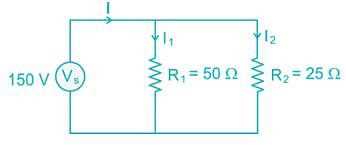
A voltage source and two resistors are connected in parallel. Suppose that Vs = 150V, R= 50Ω and R2 = 25Ω. Then each resistance contain current?

Detailed Solution for Test: Electrical Circuits- 2 - Question 4


Test: Electrical Circuits- 2 - Question 5

A current source and a voltage source are connected in series with a resistor as shown below. Suppose that Vs = 10V, is = 3A and R = 5Ω. What is the voltage across the resistor and the power absorbed by the resistor?

Detailed Solution for Test: Electrical Circuits- 2 - Question 5

Test: Electrical Circuits- 2 - Question 6

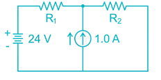
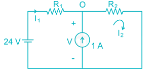
The voltage source in the given circuit supplies 24W of power. The current source supplies 6.0 W. Determine the value of the resistance R and R2:

Detailed Solution for Test: Electrical Circuits- 2 - Question 6

Given that, voltage source supplies 24 W

By applying KVL,

- 24 + I1 R1 + I2 R2 = 0

⇒ I2 R2 = 24 – R1 → (1)

Given that, current source supplies 6 W

By KVL in second loop

I2 R2 = 6 → (2)                

From (1) and (2)

⇒ R1 = 18 Ω

By KCL at point ‘O’

⇒ I2 = 1 + I1 = 2 A

We know that, I2 R2 = 6

⇒ R2 = 3 Ω

Test: Electrical Circuits- 2 - Question 7

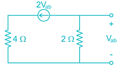
The Thevenin equivalent resistance (RTh) for the circuit shown in fig. is:
Detailed Solution for Test: Electrical Circuits- 2 - Question 7

By KCL at point ‘O’

I1 = I2 + 2 = 0.5 + 2 = 2.5

Test: Electrical Circuits- 2 - Question 8

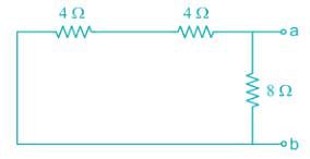
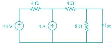
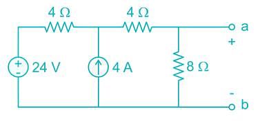
Applying Norton’s Theorem, the Norton’s equivalent circuit to the left of the terminals “a” and “b” in the below circuit is having equivalent current source (IN) and equivalent resistance (RN)
Detailed Solution for Test: Electrical Circuits- 2 - Question 8

To find Norton’s resistance, we need to short circuit the voltage source and open circuit the current source

RN = (4 + 4) || 8 = 4 Ω

To find the Norton’s current, we need to find short circuit current across terminals a-b


Test: Electrical Circuits- 2 - Question 9

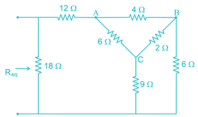
Find the value of Req in the figure given below

Detailed Solution for Test: Electrical Circuits- 2 - Question 9

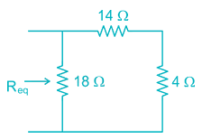
By converting Delta (ABC) in to star


Req = 18 || (14 + 4) = 9 Ω

Test: Electrical Circuits- 2 - Question 10

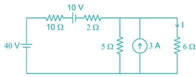
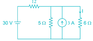
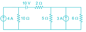
Consider the following circuit and find the current through the 6Ω resistor.
Detailed Solution for Test: Electrical Circuits- 2 - Question 10

Let the current passing through 6 Ω resistor is I.

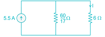
By source transformation,


By source transformation,

By current division, 

Test: Electrical Circuits- 2 - Question 11

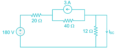
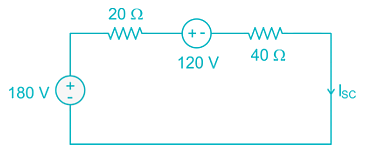
The Norton current at terminals a and b of the circuit shown at Figure:

Detailed Solution for Test: Electrical Circuits- 2 - Question 11

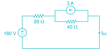
To find Norton’s current, we need to find the short circuit current across the terminals a and b.


By source transformation,

By KVL,

-180 + 20 ISC + 120 +40 ISC = 0

⇒ ISC = 1 A

Test: Electrical Circuits- 2 - Question 12

Given condition justifies which network theorems- the load impedance should be complex conjugate of the internal impedance of the active network.

Detailed Solution for Test: Electrical Circuits- 2 - Question 12

According to maximum power transfer theorem, in AC circuits the load impedance should be complex conjugate of the internal impedance of the active network

Test: Electrical Circuits- 2 - Question 13

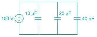
Three capacitors of 10μF, 20μF and 40μF are connected in parallel across 100 V. The total charge stored in capacitors is:

Detailed Solution for Test: Electrical Circuits- 2 - Question 13

Ceq = 10 + 20 + 40 = 70 μF

Charge, Q = CV = (70 μ F) (100 V) = 7 × 10⁻³ C

Test: Electrical Circuits- 2 - Question 14

An ac voltage is described by v(t) = 10 cos (400 πt), find out frequency and RMS value of voltage.

Detailed Solution for Test: Electrical Circuits- 2 - Question 14

V(t) = 10 cos (400 π t)

ω = 400 π

⇒ 2 π f = 400 π

⇒ f = 200 Hz

Vm = 10 V

Test: Electrical Circuits- 2 - Question 15

An inductive coil of 0.2 H is connected to 200 V, 50 Hz source. What are the inductive reactance and RMS current in the circuit?

Detailed Solution for Test: Electrical Circuits- 2 - Question 15

Given that, inductance = 0.2 H

Voltage = 200 V

Inductive reactance = 2 π fL = 2 π × 50 × 0.2 = 62.8 Ω

Test: Electrical Circuits- 2 - Question 16

A series resonant circuit has R = 2Ω, L = 1mH and C = 0.1 μF, the value of quality factor Q is:

Detailed Solution for Test: Electrical Circuits- 2 - Question 16

Given that, R = 2 Ω, L = 1 mH, C = 0.1 μ F

For series resonant circuit,

Test: Electrical Circuits- 2 - Question 17

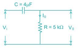
A ramp voltage V(t) = 100V is applied to an RC differentiating circuit with R = 5kΩ and C = 4μF. The maximum output voltage is

Detailed Solution for Test: Electrical Circuits- 2 - Question 17


Maximum value of V(t) = 2 V

Test: Electrical Circuits- 2 - Question 18

In an a.c. circuit, v = 50sin(ωt+60∘),i = 10cos(ωt)then the power factor of a.c. circuit will be:

Detailed Solution for Test: Electrical Circuits- 2 - Question 18

Given that, V = 50 sin (ω t + 60°)

 i = 10 cos (ω t)

i = 10 cos (ω t)

i = 10 sin (ω t + 90°)

i is leading V

Phase difference (ϕ) = 30°

Test: Electrical Circuits- 2 - Question 19

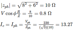
A balanced star connected load of 8 + j6 ohms per phase is connected to a 3-phase 230V supply. Power being consumed by the load is.

Detailed Solution for Test: Electrical Circuits- 2 - Question 19

Z = 8 +j 6

Power consumed by the load

= 4229.11 W

Test: Electrical Circuits- 2 - Question 20

What will be the bandwidth of a series resonant circuit provided it has an inductive reactance of 1000 Ohm, a capacitive reactance of 1000 Ohm a resistance of 0.1 Ohm? It also know that the resonant frequency is 10MHz.

Detailed Solution for Test: Electrical Circuits- 2 - Question 20

Given that, XL = 1000 Ω

XC = 1000 Ω

R = 0.1 Ω

F0 = 10 MHz


Information about Test: Electrical Circuits- 2 Page
In this test you can find the Exam questions for Test: Electrical Circuits- 2 solved & explained in the simplest way possible. Besides giving Questions and answers for Test: Electrical Circuits- 2, EduRev gives you an ample number of Online tests for practice

Top Courses for Electrical Engineering (EE)

Download as PDF

Top Courses for Electrical Engineering (EE)