Analog Electronics - 5 - Electronics and Communication Engineering (ECE) MCQ
10 Questions MCQ Test - Analog Electronics - 5

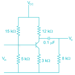
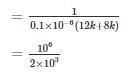
The lower 3-dB frequency of the amplifier circuit shown below is

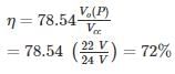
The efficiency of a class B amplifier with a supply voltage of 24V and peak output voltage Vo = 22V is _______%
| 1 Crore+ students have signed up on EduRev. Have you? Download the App |
In class AB amplifiers, the current flows through the active device for
A class – A transformer coupled, the Transistor power amplifier is Required to deliver a power output of 10 watts, the maximum power rutting of the transistor should not be less than –

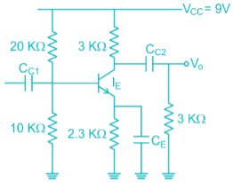
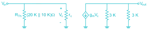
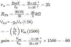
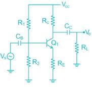
In the following transistor circuit,VBE = 0.7 V, rπ = 25 mV / IE, and β and all the capacitances are very large
The mid-band voltage gain of the amplifier is approximately
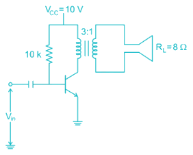
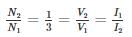
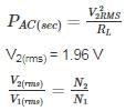
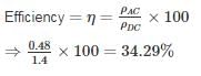
A Transformer coupled class A amplifier has a loudspeaker of 8 Ω connected or across its secondary. The Q point of collector current is 140 mA. The Turns ratio of the transformer is 3:1. If the power delivered to the load is 0.48 W. Then the rms voltage at the primary and efficiency of the transformer is
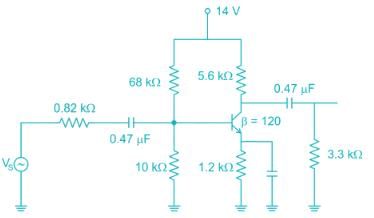
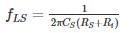
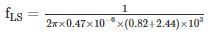
The low frequency cut-off frequency due to source capacitance (0.47 uF) is ________ Hz
Take VT = 26 mV. ( assume 0.47 uF capacitance at input is source capacitance )


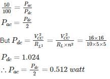
For a class A transformer coupled amplifier calculate the maximum power delivered to the load when its RL = 10 Ω, n = 5 (turns ratio) and VCC = 16 V
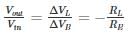
The amplifier is shown below as a voltage gain of -2.5, and input resistance of 10 kΩ and a lower 3 dB cut-off frequency of 20 Hz. Which on the following statements is TRUE when the emitter resistance RE is doubled?
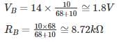
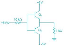
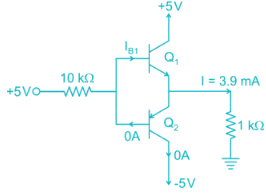
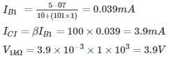
In the circuit shown in figure find the voltage drop (in V) in 1 kΩ Resistor. Assume β = 100
Top Courses for Electronics and Communication Engineering (ECE)


Important Questions for Analog Electronics - 5
Analog Electronics - 5 MCQs with Answers
Online Tests for Analog Electronics - 5
|
© EduRev
|
Education Revolution
|


|


