Electrical Engineering (EE) Exam  >  Electrical Engineering (EE) Tests  >  Test: Power Systems- 8 - Electrical Engineering (EE) MCQ

Test: Power Systems- 8 - Electrical Engineering (EE) MCQ


Test Description

10 Questions MCQ Test - Test: Power Systems- 8

Test: Power Systems- 8 for Electrical Engineering (EE) 2024 is part of Electrical Engineering (EE) preparation. The Test: Power Systems- 8 questions and answers have been prepared according to the Electrical Engineering (EE) exam syllabus.The Test: Power Systems- 8 MCQs are made for Electrical Engineering (EE) 2024 Exam. Find important definitions, questions, notes, meanings, examples, exercises, MCQs and online tests for Test: Power Systems- 8 below.
Solutions of Test: Power Systems- 8 questions in English are available as part of our course for Electrical Engineering (EE) & Test: Power Systems- 8 solutions in Hindi for Electrical Engineering (EE) course. Download more important topics, notes, lectures and mock test series for Electrical Engineering (EE) Exam by signing up for free. Attempt Test: Power Systems- 8 | 10 questions in 30 minutes | Mock test for Electrical Engineering (EE) preparation | Free important questions MCQ to study for Electrical Engineering (EE) Exam | Download free PDF with solutions
Test: Power Systems- 8 - Question 1

The steady state stability limits for round rotor and salient pole 3 – phase synchronous generator are attained at the value of power angle δ

Detailed Solution for Test: Power Systems- 8 - Question 1

Maximum steady state stability Limit 8 is attained at a power angle of 90° for round rotor and less than 90° for salient pole 3 - ϕ synchronous generator i.e 

*Answer can only contain numeric values
Test: Power Systems- 8 - Question 2

The inertial constant of 500 MVA, 13 kV generator is 8 MJ/MVA. The kinetic energy stored in the rotor at the synchronous speed is – (in MJ)


Detailed Solution for Test: Power Systems- 8 - Question 2

Inertia constant(H) =
⇒ kinetic energy stored = 500 MVA × 8 MJ/MVA

= 4000 MJ.

1 Crore+ students have signed up on EduRev. Have you? Download the App
Test: Power Systems- 8 - Question 3

An alternator is connected to an infinite bus as shown in the figure. It delivers 1.0 p.u. current at 0.707 p.f lagging at V = 1.0 p.u. The reactance Xd of the alternator is 1.4 p.u. keeping the active power fixed, if the excitation reduced, the critical excitation corresponding to operation at stability limit is ______

Detailed Solution for Test: Power Systems- 8 - Question 3

Active power output (Pe) = VI cosθ

= 0.707 p.u.

steady state power limit = EV/Xd
by keeping active power fixed if the excitation is reduced, then the critical excitation corresponding to operation at stability limit be E1.

*Answer can only contain numeric values
Test: Power Systems- 8 - Question 4

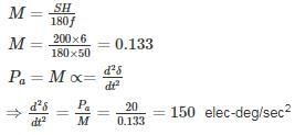
A 50 Hz. 4 pole turbo generator rated 200 MVA, 13 kV has an inertia constant of 6 MJ/MVA. If mechanical input is suddenly raised to 100 MW for an electrical load of 80 MW, then its rotor accelerations – (in elec-deg/sec2)


Detailed Solution for Test: Power Systems- 8 - Question 4

Given that,

S = 200 MVA

H = 6 MJ/MVA

F = 50 Hz

Pa = Ps – Pe = 100 – 80 = 20 Mw

Test: Power Systems- 8 - Question 5

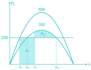
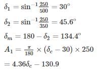
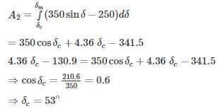
A synchronous generator is feeding 250 MW to a large 50 Hz network over a double circuit transmission line. The maximum steady state power that can be transmitted over the line with both circuits in operation is 500 MW and is 350 MW with any one of the circuits. A solid three phase fault occurring at the network end of one of the lines causes it to trip. Calculate the critical clearing angle in which the circuit breakers must trip so that synchronism is not lost.

Detailed Solution for Test: Power Systems- 8 - Question 5


*Answer can only contain numeric values
Test: Power Systems- 8 - Question 6

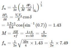
A 50 Hz synchronous generator is connected to an infinite bus through a line. The pu. reactances of the generator and the lines are j 0.4 pu and j 0.2 pu respectively. The generator no-load voltage is 1.2 pu and that of the infinite bus is 1.0 pu. The inertia constant of the generator is 4 MW-Sec/MVA. Determine the frequency (in Hz) of natural oscillations if the generator is loaded to 70% of its maximum power transfer capacity and small perturbation is given


Detailed Solution for Test: Power Systems- 8 - Question 6

fn = 1.19 Hz.

Test: Power Systems- 8 - Question 7

A generator is delivering 1.0 pu power shown in the figure. A three-phase fault occurs at point F. The critical clearing angle for clearing the fault with simultaneous opening of breaker 1 and 2 is

Detailed Solution for Test: Power Systems- 8 - Question 7

Before fault, x1eq = j0.1 + (j0.6||j0.6) + j0.1


= j0.1 + j0.3 + j0.1 = j0.5
After fault, x3eq = j0.8
= 126.86° = 2.214 rad

⇒ δc = 41.15° 

*Answer can only contain numeric values
Test: Power Systems- 8 - Question 8

A 100 MVA generator operates on full load of 50 Hz frequency. The load is suddenly reduced to 60 MW. The system value begins to close only after 0.5 sec. and if the value of the inertia constant (H) is 4 MJ/MVA, then the frequency at 0.5 sec is – (in Hz)


Detailed Solution for Test: Power Systems- 8 - Question 8


⇒ KE = 400 MJ

KE stored in 0.5 sec = 60 × 0.5 = 30 MJ

KE is directly proportional to square of the frequency

⇒ f = 51.84 Hz

*Answer can only contain numeric values
Test: Power Systems- 8 - Question 9

In a power system has pre-fault voltage 1 PU and ZBUS given as

If 3ϕ fault occur at bus 3 find the post-fault voltage at bus 2 is ______ (in PU)


Detailed Solution for Test: Power Systems- 8 - Question 9

Test: Power Systems- 8 - Question 10

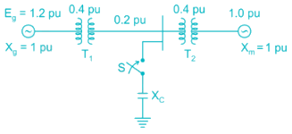
In the system shown in the figure, a static three-phase capacitor of reactance 1 pu per phase is connected through a switch at motor bus bar. The internal voltage and reactances are specified. The steady state power limits when the switch is open and closed respectively are
Detailed Solution for Test: Power Systems- 8 - Question 10

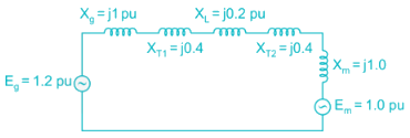
When switch is open, the reactance diagram is

xeq = j1 + j0.4 + j0.2 + j1 = j3.0 pu

Steady state power limit = 
= 0.4 pu

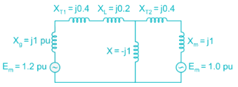
When switch is closed, the reactance diagram is


By converting star in to delta,


= 0.76 pu
Steady state power limit = 
= 1.58 pu

Information about Test: Power Systems- 8 Page
In this test you can find the Exam questions for Test: Power Systems- 8 solved & explained in the simplest way possible. Besides giving Questions and answers for Test: Power Systems- 8, EduRev gives you an ample number of Online tests for practice

Top Courses for Electrical Engineering (EE)

Download as PDF

Top Courses for Electrical Engineering (EE)