Electrical Engineering (EE) Exam  >  Electrical Engineering (EE) Tests  >  Test: Electrical & Electronic Measurements- 6 - Electrical Engineering (EE) MCQ

Test: Electrical & Electronic Measurements- 6 - Electrical Engineering (EE) MCQ


Test Description

10 Questions MCQ Test - Test: Electrical & Electronic Measurements- 6

Test: Electrical & Electronic Measurements- 6 for Electrical Engineering (EE) 2024 is part of Electrical Engineering (EE) preparation. The Test: Electrical & Electronic Measurements- 6 questions and answers have been prepared according to the Electrical Engineering (EE) exam syllabus.The Test: Electrical & Electronic Measurements- 6 MCQs are made for Electrical Engineering (EE) 2024 Exam. Find important definitions, questions, notes, meanings, examples, exercises, MCQs and online tests for Test: Electrical & Electronic Measurements- 6 below.
Solutions of Test: Electrical & Electronic Measurements- 6 questions in English are available as part of our course for Electrical Engineering (EE) & Test: Electrical & Electronic Measurements- 6 solutions in Hindi for Electrical Engineering (EE) course. Download more important topics, notes, lectures and mock test series for Electrical Engineering (EE) Exam by signing up for free. Attempt Test: Electrical & Electronic Measurements- 6 | 10 questions in 30 minutes | Mock test for Electrical Engineering (EE) preparation | Free important questions MCQ to study for Electrical Engineering (EE) Exam | Download free PDF with solutions
*Answer can only contain numeric values
Test: Electrical & Electronic Measurements- 6 - Question 1

A 3 ½ digit dual slope integrated DVM, 2 V full scale is used to measure a time varying voltage V(t) = 1.0 + 2 sin 50 πt. The voltmeter indicates


Detailed Solution for Test: Electrical & Electronic Measurements- 6 - Question 1

V(t) = 1 + 2 sin 50 πt
Dual slope integrated DVM measures the average value of input.
Vavg = 1 V
Hence the meter reading will be 1.000 V

*Answer can only contain numeric values
Test: Electrical & Electronic Measurements- 6 - Question 2

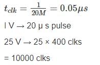
A digital voltmeter uses a 20 MHZ clock and has a voltage controlled generation switch provides a width of 20 μ sec per volt of unit signal. 25 V of input signal would correspond to pulse count of –


Detailed Solution for Test: Electrical & Electronic Measurements- 6 - Question 2

1 Crore+ students have signed up on EduRev. Have you? Download the App
*Answer can only contain numeric values
Test: Electrical & Electronic Measurements- 6 - Question 3

In a digital voltmeter, the oscillator frequency is 400 kHz and the ramp voltage falls from 8V to 0V in 20m sec. The number of pulse counted by the counter is


Detailed Solution for Test: Electrical & Electronic Measurements- 6 - Question 3

Frequency = 400 kHz.
fclk = 400kHz
t = 20m sec
⇒ Clock pulses, n = t fclk = 20m sec × 400 kHz = 8000

Test: Electrical & Electronic Measurements- 6 - Question 4

How would a reading 0.6973 V be displayed on  digit digital voltmeter on its 10 V scale.

Detailed Solution for Test: Electrical & Electronic Measurements- 6 - Question 4

Resolution on 10 V scale 
N = no. of full bits

Reading of 0.6973 = 0.697 volts

*Answer can only contain numeric values
Test: Electrical & Electronic Measurements- 6 - Question 5

A 200 mV full scale dual-slope 3 ½ digit DMM has a reference voltage of 100 mV and a first integration time of 100 ms. For an input of [100 + 10  Cos (100πt)] mV, the conversion time (without taking the auto-zero phase time into consideration) in millisecond is______.


Detailed Solution for Test: Electrical & Electronic Measurements- 6 - Question 5

Given that, Vref = 100 mV
T1 = 100 msec
in = 100 mV
We know that,
Vin T1 = Vref T2
⇒ (100) (100) = (100) (T2)
⇒ T2 = 100 msec
Total conversion time
T = T1 + T2
T = 100 + 100 = 200 ms

Test: Electrical & Electronic Measurements- 6 - Question 6

A rectifier type instrument uses a bridge rectifier and has its scale calibrated in terms of rms values of a sine wave. It indicates a voltage of 2.22 V. When measuring a voltage of triangular wave shape. Estimate the error –

Detailed Solution for Test: Electrical & Electronic Measurements- 6 - Question 6

The meter uses a full wave rectifier circuit it indicates value of 2.22 V the form factor for full wave rectified sinusoidal waveform is 1.11 
Average value of voltage,
Vavg = 2 V
For triangular wave shape, peak value of voltage Vm = 2 Vavg = 4 V

*Answer can only contain numeric values
Test: Electrical & Electronic Measurements- 6 - Question 7

A dual slope integrating type A/D converter has 5 μF capacitor and 25 kΩ resistor connected to it. If the reference voltage is taken as 10 V and output voltage of integrator cannot exceed 10 V then time for which reference voltage can be integrated will be – (in msec)


Detailed Solution for Test: Electrical & Electronic Measurements- 6 - Question 7

The output voltage of dual slope integrating type AD converter,

= 80 t
Given that, output voltage cannot exceed 10 V
⇒ 80 t = 10 ⇒ 125 msec

Test: Electrical & Electronic Measurements- 6 - Question 8

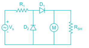
In a multimeter circuit, for a.c. voltage measurement, what is the function of diode D2?
Detailed Solution for Test: Electrical & Electronic Measurements- 6 - Question 8

In the absence of D2, leakage current would have flowed in D1. To bypass this reverse leakage current of D1 during the negative half cycle of the input. The absence of D2 reduces the average value for complete cycle than it would have been in half wave rectification.

*Answer can only contain numeric values
Test: Electrical & Electronic Measurements- 6 - Question 9

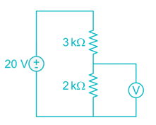
Determine the error percentage of the voltage reading due to the insertion of a voltmeter. R1 = 3 kΩ, R2 = 2 kΩ and the internal resistance of the voltmeter is 40 kΩ.

Detailed Solution for Test: Electrical & Electronic Measurements- 6 - Question 9

The actual voltage of R2 is:

The voltage after inserting the voltmeter will then be

Thus, error percentage

Test: Electrical & Electronic Measurements- 6 - Question 10

Which meter has a greater sensitivity meter A having a range of 0 - 15 V and a multiplier resistance of 22 kΩ, or meter B with a range of 0 - 300 V and multiplier resistance of 324 kΩ? Both meter moments have a resistance of 2 kΩ.

Detailed Solution for Test: Electrical & Electronic Measurements- 6 - Question 10

Meter A:
Total resistance = 2 + 22 = 24 kΩ

Meter B:
Total resistance = 2 + 324 = 326 kΩ

Meter A is more sensitive

Information about Test: Electrical & Electronic Measurements- 6 Page
In this test you can find the Exam questions for Test: Electrical & Electronic Measurements- 6 solved & explained in the simplest way possible. Besides giving Questions and answers for Test: Electrical & Electronic Measurements- 6, EduRev gives you an ample number of Online tests for practice

Top Courses for Electrical Engineering (EE)

Download as PDF

Top Courses for Electrical Engineering (EE)