Current Electricity NAT Level - 2 - Physics MCQ
10 Questions MCQ Test - Current Electricity NAT Level - 2
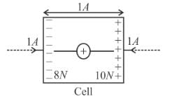
Figure shows a cell in which unit positive charge experience a constant non electric force of 10N and a constant electric force of 8N in directions shown in the figure. Find the emf of the cell, difference across the cell (in volt)

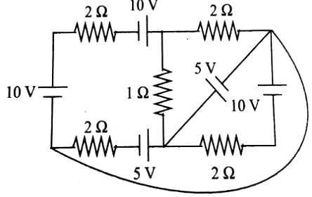
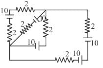
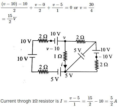
In the circuit diagram shown in find the current through the 1Ω resistor.

| 1 Crore+ students have signed up on EduRev. Have you? Download the App |
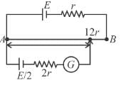
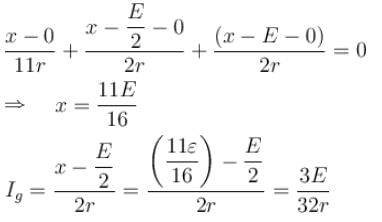
Consider the potentiometer circuit arranged as in figure. The potentiometer wire AB is 300cm long. If the jockey touches the wire at a distance of 275cm from A, then (3E/Nr) current flow through galvanometer. Find value of N.

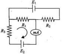
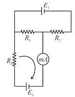
The circuit shown in the figure contains three resistors R1 =100Ω, R2 = 50Ω, and R3 = 50Ω and cells of emf’s E1 = 2V and E2. The ammeter indicates a current of 50mA. Determine the current (mA) in the resistor R2 :
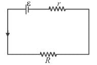
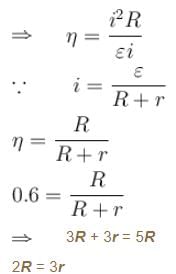
The efficiency of a cell when connected to a resistance R is 60%. What will be its efficiency (in %) if the external resistance is increased to six times.
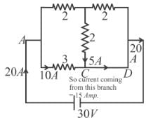
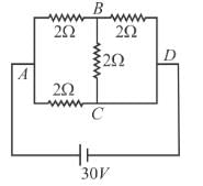
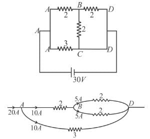
Find current in the branch CD of the circuit (in ampere).
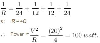
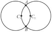
Two circular rings of identical radii and resistance of 36Ω each are placed in such a way that they cross each other’s centre C1 and C2 as shown in figure. Conducting joints are made at intersection points A and B of the rings. An ideal cell of emf 20 volts is connected across AB. The power delivered (in watt) by cell is :
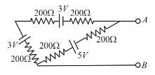
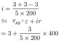
In the circuit shown all five resistors have the same value 200 ohms and each cell has an emf 3 volts, if the open circuit voltage is x/10 volt then x is :
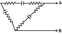
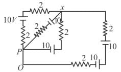
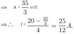
All batteries are having emf 10 volt and internal resistance negligible. All resistors are in ohms. Calculate the current in the right most 2Ω resistor.
Two cylinderical rods of uniform cross-section area A and 2A, having free electrons per unit volume 2n and n respectively are joined in series. A current I flows through them in steady state. Then the ratio of drift velocity of free electron in left rod to drift velocity of electron in the right rod is  is :
is :







 D branch = 5 Amp.