Physics Exam  >  Physics Tests  >  Test: Electronics - 3 - Physics MCQ

Test: Electronics - 3 - Physics MCQ


Test Description

20 Questions MCQ Test - Test: Electronics - 3

Test: Electronics - 3 for Physics 2024 is part of Physics preparation. The Test: Electronics - 3 questions and answers have been prepared according to the Physics exam syllabus.The Test: Electronics - 3 MCQs are made for Physics 2024 Exam. Find important definitions, questions, notes, meanings, examples, exercises, MCQs and online tests for Test: Electronics - 3 below.
Solutions of Test: Electronics - 3 questions in English are available as part of our course for Physics & Test: Electronics - 3 solutions in Hindi for Physics course. Download more important topics, notes, lectures and mock test series for Physics Exam by signing up for free. Attempt Test: Electronics - 3 | 20 questions in 40 minutes | Mock test for Physics preparation | Free important questions MCQ to study for Physics Exam | Download free PDF with solutions
Test: Electronics - 3 - Question 1

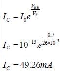
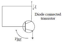
For an n-p-n transistor connected as shown in figure VBE = 0.7 volts. Given that reverse saturation current of the junction at room temperature 300° AT is 10-13 A. the emitter current is

Detailed Solution for Test: Electronics - 3 - Question 1


*Answer can only contain numeric values
Test: Electronics - 3 - Question 2

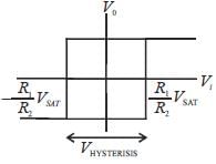
In the bistable circuit shown in the figure, the ideal OP- Amp lias saturation levels of ± 5 V. The value of R1 (in kΩ) that gives a hysteresis width of 500 mV is__________
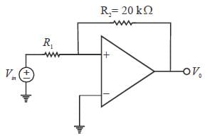
(Answer should be an integer)


Detailed Solution for Test: Electronics - 3 - Question 2


1 Crore+ students have signed up on EduRev. Have you? Download the App
Test: Electronics - 3 - Question 3

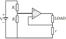
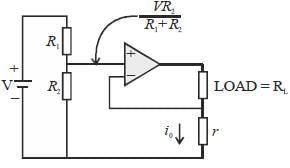
The circuit shown in the figure is

Detailed Solution for Test: Electronics - 3 - Question 3


i0 output current independent of Load and i0 ∝ V . Hence, voltage control current source.

Test: Electronics - 3 - Question 4

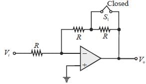
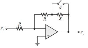
Let the magnitude of the gain in the inverting Op-Amp circuit shown be x with switch S1 open. When the switch is closed, the magnitude of gain becomes.
Detailed Solution for Test: Electronics - 3 - Question 4

Case - I: Switch open

Case - II:

*Answer can only contain numeric values
Test: Electronics - 3 - Question 5

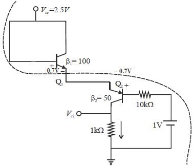
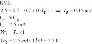
Consider the circuit shown in the figure. Assuming VBE1 = VEB2 = 0.7V, the value of the dc voltage VC2 (in volt) is ___________ .
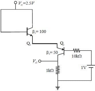
(Round off to one decimal place)


Detailed Solution for Test: Electronics - 3 - Question 5


Test: Electronics - 3 - Question 6

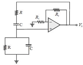
A Wein bridge oscillator is shown in figure, which of the following statements are true, if 'f' is the frequency of oscillation?
Detailed Solution for Test: Electronics - 3 - Question 6

The frequency of Wein bridge oscillator is given by 
Put value & verify; we get the correct option is (a)

Test: Electronics - 3 - Question 7

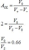
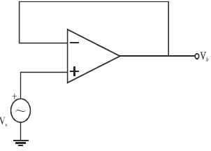
In a voltage follower op-amp circuit, find the closed loop gain V0/Vs if the open loop gain = 2
Detailed Solution for Test: Electronics - 3 - Question 7

Test: Electronics - 3 - Question 8

The circuit shown in figure is best described as a

Detailed Solution for Test: Electronics - 3 - Question 8

CKT is voltage doubles circuit
⇒ Once capacitor charge it can't discarge

Test: Electronics - 3 - Question 9

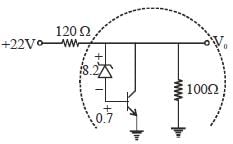
In the shunt regulator shown below, the Vz 8.2 V and VBE = 0.7 V. The regulated output voltage V0 is
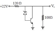
Detailed Solution for Test: Electronics - 3 - Question 9

KVL


Test: Electronics - 3 - Question 10

Let  denote the Exclusive OR (XOR) operation. Let '1' and '0' denote the binary constants. Consider the following Boolean expression for F over two variables P and Q :

The equivalent expression for F is

Detailed Solution for Test: Electronics - 3 - Question 10


We Know: 


Test: Electronics - 3 - Question 11

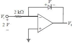
In the Op-Amp circuit shown, assume that the diode current follows the equation I = Is exp (V/VT). For V, = 2V, V0 = V01 and for Vi = 4V, V0 = V02, The relationsliip between V01 and V02 is
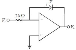
Detailed Solution for Test: Electronics - 3 - Question 11

Logarithmic Amplifies
Case - I


Similarly Case - II


∴ 

Test: Electronics - 3 - Question 12

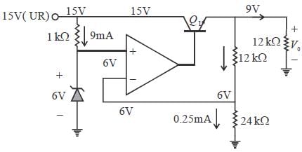
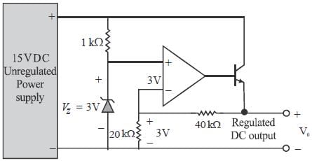
A regulated power supply, shown in figure below, lias an unregulated input (UR) of 15 volts and generates a regulated ouput. Use the component values shown in the figure.
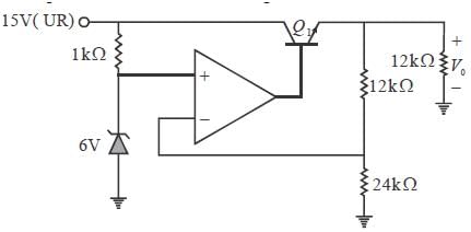
The power dissipation across the transistor Q1 shown in the figure is 

Detailed Solution for Test: Electronics - 3 - Question 12


Test: Electronics - 3 - Question 13

The output voltage of the regulated power supply shown in figure is
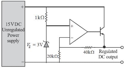
Detailed Solution for Test: Electronics - 3 - Question 13


Voltage divison Rule

*Answer can only contain numeric values
Test: Electronics - 3 - Question 14

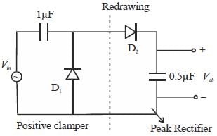
In the circuit shown, assume that diodes D1 and D2 are ideal. In the steady-state condition, the average voltage Vab (in Volts) across the 0.5 μF capacitor is
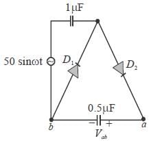
(Answer should be an integer)


Detailed Solution for Test: Electronics - 3 - Question 14


*Answer can only contain numeric values
Test: Electronics - 3 - Question 15

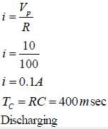
The figure shows a half-wave rectifier. The diode D is ideal. The average steady state current (inAmperes) through the diode is approximately____________
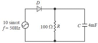
(Answer should be an integer)


Detailed Solution for Test: Electronics - 3 - Question 15

Positive peak detector circuit

*Answer can only contain numeric values
Test: Electronics - 3 - Question 16

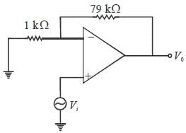
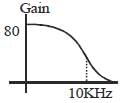
The amplifier circuit shown in the figure is implemented using a compensated operational amplier (OP-Amp), and has an open-loop voltage gain, A0 = 105 V/V and an open-loop cut-off frequency, fc = 8 Hz.

The voltage gain of the amplifier at 15 kHz. in V/V, is_______________
(Round off to two decimal places)


Detailed Solution for Test: Electronics - 3 - Question 16


" Put value"    Voltage divison Rule

Gain BW product = Gain BW
For open loop     product


*Answer can only contain numeric values
Test: Electronics - 3 - Question 17

Consider the circuit shown in the figure Assume base-to-emitter voltage VBE - 0.8 V. and common base current gain(α) of the transistor is unity.
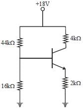
The value of the collector-to-emitter voltage VCE(in volts) is_________________.
(Answer should be an integer)


Detailed Solution for Test: Electronics - 3 - Question 17

Given α = 1


*Answer can only contain numeric values
Test: Electronics - 3 - Question 18

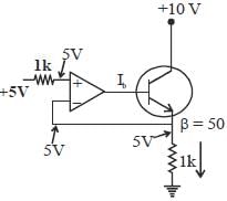
For the given circuit, value of the base current ( Ib) of the npn transistor will be___________mA.
(β is the current gain and assume Op-Amp as ideal).
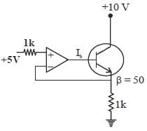
(Round off to three decimal places)


Detailed Solution for Test: Electronics - 3 - Question 18


Test: Electronics - 3 - Question 19

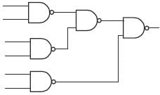
Transform the following logic circuit (without expressing its switching function) into an equivalent logic circuit that employs only NAND gates each with 2-inputs.

Detailed Solution for Test: Electronics - 3 - Question 19


( 5 NAND Gate)

*Answer can only contain numeric values
Test: Electronics - 3 - Question 20

The number ofNAND sate required to implement y =  is__________
(Answer should be an integer)


Detailed Solution for Test: Electronics - 3 - Question 20


Simplify, distributive law.


Total 2 NAND gate

Information about Test: Electronics - 3 Page
In this test you can find the Exam questions for Test: Electronics - 3 solved & explained in the simplest way possible. Besides giving Questions and answers for Test: Electronics - 3, EduRev gives you an ample number of Online tests for practice
Download as PDF