Electrical Engineering (EE) Exam  >  Electrical Engineering (EE) Tests  >  Test: Coupled Circuits - 3 - Electrical Engineering (EE) MCQ

Test: Coupled Circuits - 3 - Electrical Engineering (EE) MCQ


Test Description

10 Questions MCQ Test - Test: Coupled Circuits - 3

Test: Coupled Circuits - 3 for Electrical Engineering (EE) 2024 is part of Electrical Engineering (EE) preparation. The Test: Coupled Circuits - 3 questions and answers have been prepared according to the Electrical Engineering (EE) exam syllabus.The Test: Coupled Circuits - 3 MCQs are made for Electrical Engineering (EE) 2024 Exam. Find important definitions, questions, notes, meanings, examples, exercises, MCQs and online tests for Test: Coupled Circuits - 3 below.
Solutions of Test: Coupled Circuits - 3 questions in English are available as part of our course for Electrical Engineering (EE) & Test: Coupled Circuits - 3 solutions in Hindi for Electrical Engineering (EE) course. Download more important topics, notes, lectures and mock test series for Electrical Engineering (EE) Exam by signing up for free. Attempt Test: Coupled Circuits - 3 | 10 questions in 30 minutes | Mock test for Electrical Engineering (EE) preparation | Free important questions MCQ to study for Electrical Engineering (EE) Exam | Download free PDF with solutions
Test: Coupled Circuits - 3 - Question 1

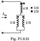
Leq =?

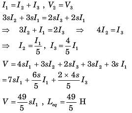
Detailed Solution for Test: Coupled Circuits - 3 - Question 1

Let I1 be the current through 4 H inductor and I2 and I3 be the current through 3 H, and 2 H inductor respectively

Test: Coupled Circuits - 3 - Question 2

Consider the circuit shown in fig. P1.9.22–24.
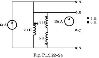
Q. The voltage VAG of terminal AD is

Detailed Solution for Test: Coupled Circuits - 3 - Question 2

1 Crore+ students have signed up on EduRev. Have you? Download the App
Test: Coupled Circuits - 3 - Question 3

Consider the circuit shown in fig. P1.9.22–24.
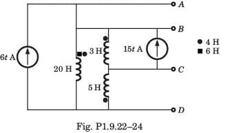
Q. The voltage vBG of terminal BD is

Detailed Solution for Test: Coupled Circuits - 3 - Question 3

Test: Coupled Circuits - 3 - Question 4

Consider the circuit shown in fig. P1.9.22–24.
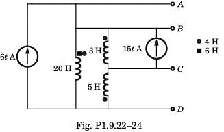
Q. The voltage vCG of terminal CD is

Detailed Solution for Test: Coupled Circuits - 3 - Question 4

Test: Coupled Circuits - 3 - Question 5

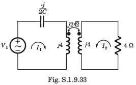
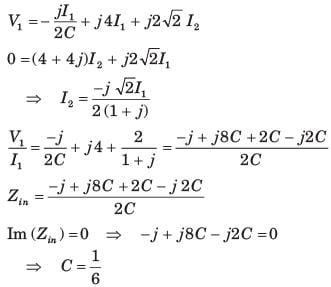
In the circuit of fig. P1.9.33 the ω = 2 rad/s. The resonance occurs when C is
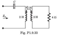
Detailed Solution for Test: Coupled Circuits - 3 - Question 5


Test: Coupled Circuits - 3 - Question 6

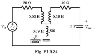
In the circuit of fig. P1.9.34, the voltage gain is zero at ω = 333.33 rad/s. The value of C is
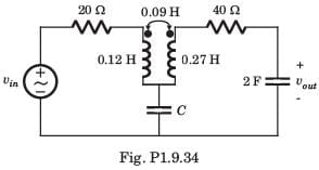
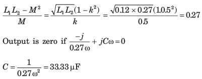
Detailed Solution for Test: Coupled Circuits - 3 - Question 6


Test: Coupled Circuits - 3 - Question 7

In the circuit of fig. P1.9.35 at ω = 333.33 rad/s, the voltage gain vout/vin is zero. The value of C is
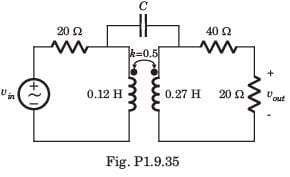
Detailed Solution for Test: Coupled Circuits - 3 - Question 7

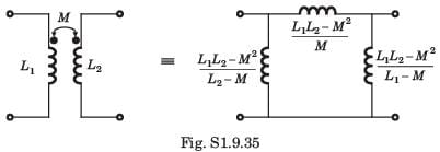
The π  equivalent circuit of coupled coil is shown in fig. S1.9.35

Test: Coupled Circuits - 3 - Question 8

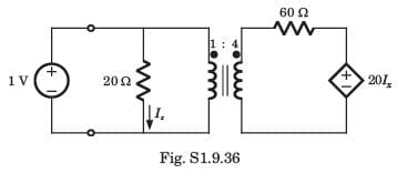
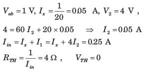
The Thevenin equivalent at terminal ab for the network shown in fig. P1.9.36 is
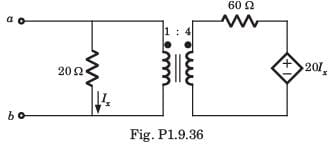
Detailed Solution for Test: Coupled Circuits - 3 - Question 8

Applying 1 V test source at ab terminal,

Test: Coupled Circuits - 3 - Question 9

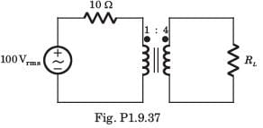
In the circuit of fig. P1.9.37 the maximum power delivered to RL is
Detailed Solution for Test: Coupled Circuits - 3 - Question 9

Impedance seen by RL = 10 x 42 = 160 Ω
For maximum power RL = 160 Ω, Zo = 10Ω

Test: Coupled Circuits - 3 - Question 10

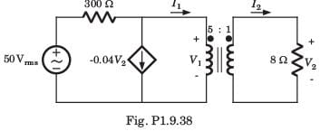
The average power delivered to the 8Ω load in the circuit of fig. P1.9.38 is
Detailed Solution for Test: Coupled Circuits - 3 - Question 10

Information about Test: Coupled Circuits - 3 Page
In this test you can find the Exam questions for Test: Coupled Circuits - 3 solved & explained in the simplest way possible. Besides giving Questions and answers for Test: Coupled Circuits - 3, EduRev gives you an ample number of Online tests for practice

Top Courses for Electrical Engineering (EE)

Download as PDF

Top Courses for Electrical Engineering (EE)