Electrical Engineering (EE) Exam  >  Electrical Engineering (EE) Tests  >  Test: Sequential Logic Circuits- 2 - Electrical Engineering (EE) MCQ

Test: Sequential Logic Circuits- 2 - Electrical Engineering (EE) MCQ


Test Description

15 Questions MCQ Test - Test: Sequential Logic Circuits- 2

Test: Sequential Logic Circuits- 2 for Electrical Engineering (EE) 2024 is part of Electrical Engineering (EE) preparation. The Test: Sequential Logic Circuits- 2 questions and answers have been prepared according to the Electrical Engineering (EE) exam syllabus.The Test: Sequential Logic Circuits- 2 MCQs are made for Electrical Engineering (EE) 2024 Exam. Find important definitions, questions, notes, meanings, examples, exercises, MCQs and online tests for Test: Sequential Logic Circuits- 2 below.
Solutions of Test: Sequential Logic Circuits- 2 questions in English are available as part of our course for Electrical Engineering (EE) & Test: Sequential Logic Circuits- 2 solutions in Hindi for Electrical Engineering (EE) course. Download more important topics, notes, lectures and mock test series for Electrical Engineering (EE) Exam by signing up for free. Attempt Test: Sequential Logic Circuits- 2 | 15 questions in 45 minutes | Mock test for Electrical Engineering (EE) preparation | Free important questions MCQ to study for Electrical Engineering (EE) Exam | Download free PDF with solutions
Test: Sequential Logic Circuits- 2 - Question 1

Assertion (A): The indeterminate condition of the J-K flip-flop is permitted in S-R flip-flop.
Reason (R): A J-Kfiip-flop has a characteristic similar to that of an S-R flip-flop.

Detailed Solution for Test: Sequential Logic Circuits- 2 - Question 1

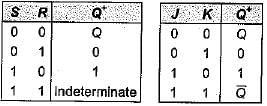
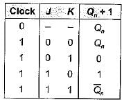
The truth table for S-ffand J-Kflip-flop are shown below.

It is clear from the above truth table that when S = R = 1, the output of S-R flip-flop is indeterminate. However, when J = K = 1, the output of J-Kflip-flop is (not indeterminate). Therefore, the indeterminate condition of the S-R flip-flop is permitted in a J-Kflip-flop.
A J-Kflip-flop has a characteristic similar to that of an S-R flip-flop which is evident from the above truth tables.
Hence, assertion is false but reason is true.

Test: Sequential Logic Circuits- 2 - Question 2

The J-K master-slave flip-flops in figure shown below has its J and K inputs tied to + VCC and a series of pulses is applied to its CLK input.

The waveform at G is given by

Detailed Solution for Test: Sequential Logic Circuits- 2 - Question 2

Let the flip-flop is initially reset.
The truth table for aiven circuit is shown below

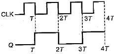
Thus, the waveform for Q will be as shown below

1 Crore+ students have signed up on EduRev. Have you? Download the App
Test: Sequential Logic Circuits- 2 - Question 3

For the J-Kflip-flop shown below to function as a divide-by-2 element, the J and K inputs should be equal to

Detailed Solution for Test: Sequential Logic Circuits- 2 - Question 3

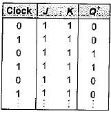
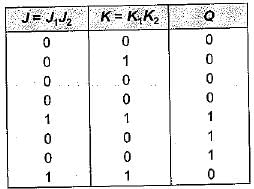
If J = K = 1, then the truth table will be as show below (Initially flip-flop is.reset).

Thus, the given J-Kflip-flop will work as a divide- by-2 elemen

Test: Sequential Logic Circuits- 2 - Question 4

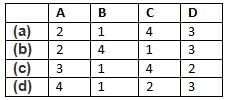
Match List-l with List-II and select the correct answer using the codes given below the lists:
List-I
A. J-K flip-flop
B. D flip-flop
C. Master-slave flip-flop
D. T flip-flop
List-lI
1. Transparent latch
2. Most versatile and widely used of all the flip flops
3. Not widely available as commercial items
4. Pulse triggered flip-flop
Codes:
Detailed Solution for Test: Sequential Logic Circuits- 2 - Question 4

• The J-K flip-flop is the most versatile and most widely used of all the flip-flops.
• Transparent latch is associated with D-flip flop since the clocked D latch is called a transparent D latch, because its output follows the input when the clock is HIGH.
• Master-slave flip-flops are called pulse- triggered flip-flops, because the length of time required for its output to change state equals the width of one (clock) pulse.
• T flip -flop is not widely available as commercial items.

Test: Sequential Logic Circuits- 2 - Question 5

Assertion (A): An unclocked flip-flop is called a latch.​
Reason (R): A latch is constructed using two cross-coupled NAND gates or NOR gates.

Detailed Solution for Test: Sequential Logic Circuits- 2 - Question 5

An unclocked flip-flop is called a latch, because the output of the flip-flop latches on to ‘1’ or ‘0' immediately after the input is applied. Hence, assertion is a correct statement. Reason is also a true statement but not the correct explanation of assertion.

Test: Sequential Logic Circuits- 2 - Question 6

Consider the following statements associated with flip-flops;
1. Any one type of flip-flop can be converted to any other type by providing a suitable combinational circuit.
2. The inputs to a master-slave flip-flop must change when the clock is HIGH.
3. In a master-slave flip-flop, master is level triggered while slave is edge triggered.
4.  Data lock-out flip-flops are nothing but master-slave flip-flops.

Q. Which of the statements given above is/are not correct?

Detailed Solution for Test: Sequential Logic Circuits- 2 - Question 6

• Statement-1 is correct.
• The inputs to a master-slave flip-flops must not change when the clock is HIGH. If they change, the flip-flop gives an output corresponding to the last combination of inputs present before the dock terminals. Hence, statement-2 is not correct.
• In a master-slave flip-flop, master is edge-triggered while slave is level triggered. Thus, statements-3 is not correct.
• Data lock-out flip-flops are nothing but master-slave flip-flops in which the master is an edge triggered flip-flop. Thus, statement-4 is correct.

Test: Sequential Logic Circuits- 2 - Question 7

For the flip-flop shown below, there is one clock pulse for each bit time.
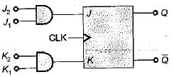
If the following serial data are applied to the flip-flop, then the resulting decimal value of the serial data that appears on the Q output will be (assume that, Q is initially ‘0’)
J1 = 01101101 ; J2 =10011011
K1 = 01101001 ; K2 = 11011011

Detailed Solution for Test: Sequential Logic Circuits- 2 - Question 7

Q = 0 (Initially)

Thus, serial output data at Q
= 00001110 = 14 (Decimal value)

Test: Sequential Logic Circuits- 2 - Question 8

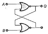
For a flip-flop formed from two NOR gates as shown in figure the unusable state corresponds to
Detailed Solution for Test: Sequential Logic Circuits- 2 - Question 8

Given flip-flop represents S-R latch using NOR gates.
When A = 1, B = 1 we will get invalid or unusable state.

Test: Sequential Logic Circuits- 2 - Question 9

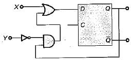
The digital circuit as shown below represents to which one of the following?
Detailed Solution for Test: Sequential Logic Circuits- 2 - Question 9

Here, 
If X = S and Y = R then, the given circuit circuit represents S-R flip-flop using D flip-flop

Test: Sequential Logic Circuits- 2 - Question 10

If tp is the pulse width, Δt is the propagation delay, T is period of pulse train then which of the following condition can avoid the race around condition?

Detailed Solution for Test: Sequential Logic Circuits- 2 - Question 10

Race around condition occurs in J-K flip-flop when J = K = 1. This condition can be avoided if the propagation delay of flip-flop is more than pulse-width of the clock but less than the clock.
i.e. 2tp < Δt < T

Test: Sequential Logic Circuits- 2 - Question 11

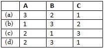
Match List-I (Logic Circuit) with List-ll (Circuit Realization) and select the correct answer using the codes given below the lists:
List-I
A. J-K flip-flop
B. T flip-flop
C. D fiip-flop
List-ll
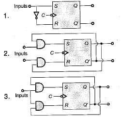
Codes:
Detailed Solution for Test: Sequential Logic Circuits- 2 - Question 11

For conversion of S-R flip-flop to
A. J-K flip flop:
S = JQ' and R = KQ
B. T Flip-flop:
S = TQ' and = TQ
C. D flip-flop:

Test: Sequential Logic Circuits- 2 - Question 12

The characteristic equation of a T flip-flop is given by

Detailed Solution for Test: Sequential Logic Circuits- 2 - Question 12

For a T flip-flop, Qn+1

Test: Sequential Logic Circuits- 2 - Question 13

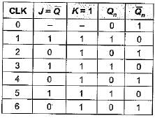
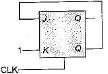
In a J-Kflip-flop we have (shown in figure). Assuming the flip-flop was initially cleared and then clocked for 6-pulses, the sequence at the Q output will be
Detailed Solution for Test: Sequential Logic Circuits- 2 - Question 13

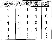
The truth table will be as shown below.

Thus, output Q for 6 clock pulse = 101010.

Test: Sequential Logic Circuits- 2 - Question 14

The output of a J-Kflip-flop Qn is ‘0’. The state of the flip-flop changes when a clock pulse is applied. The possible combination of Jn and Kn inputs could be (‘X' denote don’t care)

Detailed Solution for Test: Sequential Logic Circuits- 2 - Question 14

The truth table of J-K flip-flop is shown below.

Given, Qn = 0 initially,
When clock pulse is applied, the state of FF changes to ‘1’ i.e. Qn+ 1 = 1, which is possible,
if, ' J = 1, K = 0 ...(i)
or, Jn = 1 , Kn = ‘X’ ...(ii)
Thus, Jn = 1 and Kn = ‘X (don't care) satisfy the above two conditions.

Test: Sequential Logic Circuits- 2 - Question 15

When a flip-flop is reset, its output will be

Detailed Solution for Test: Sequential Logic Circuits- 2 - Question 15

A FF is set when Q = 1, 
A FF is reset when  Q = 0 ; 

Information about Test: Sequential Logic Circuits- 2 Page
In this test you can find the Exam questions for Test: Sequential Logic Circuits- 2 solved & explained in the simplest way possible. Besides giving Questions and answers for Test: Sequential Logic Circuits- 2, EduRev gives you an ample number of Online tests for practice

Top Courses for Electrical Engineering (EE)

Download as PDF

Top Courses for Electrical Engineering (EE)