Part Test- 2 (JEE Main 2018) - JEE MCQ
30 Questions MCQ Test - Part Test- 2 (JEE Main 2018)
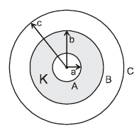
A and C are concentric conducting spherical shells of radius a and c respectively. A is surrounded by a concentric dielectric medium of inner radius a, outer radius b and dielectric constant K as shown in the figure. If sphere A is given a charge Q, the potential at the outer surface of the dielectric is.

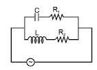
In the given circuit the rms value of voltage across the capacitor C, inductor L and resister R1 are 12V, 10V and 5V respectively. Then the peak voltage across R2 is

| 1 Crore+ students have signed up on EduRev. Have you? Download the App |
Two identical capacitors C1 and C2 are connected in series with a battery. They are fully charged. Now a dielectric slab is inserted between the plates of C2. The potential difference across C1 will :

A solenoid having an iron core has its terminals connected across an ideal DC source. If the iron core is removed, the current flowing through the solenoid
An electric field ‘E’ whose direction is radially outward varies as distance from origin ‘r’ as shown in the graph. E is taken as positive if its direction is away from the origin. Then the work done by electric field on a 2 C charge if it is taken from (1, 1, 0) to (3, 0, 0) is
A negative test charge is moving near a long straight current carrying wire . A force will act on the test charge in a direction parallel to the direction of the current, if the motion of the charge is in a direction:
Potential difference between centre and the surface of sphere of radius R and having uniform volume charge density ρ within it will be :
The magnetic field at the origin due to the current flowing in the wire is
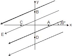
There exists a uniform electric field in the space as shown. Four points A, B, C and D are marked which are equidistant from the origin. If VA, VB, VC and VD are their potentials respectively, then

A current carrying wire AB of the length L is turned along a circle, as shown in figure. The magnetic field at the centre O.
Total electric force on an electric dipole placed in an electric field of a point charge is:
The magnitude of magnetic field at O (centre of the circular part) due to the current carrying coil as shown is :
Eight point charges (can be assumed as small spheres uniformly charged and their centres at the corner of the cube) having values q each are fixed at vertices of a cube. The electric flux through square surface ABCD of the cube is
A charged particle is moving in the region around a long current carrying wire. Due to wire, it may experience:
The figure shows a charge q placed inside a cavity in an uncharged conductor.
Now if an external electric field is switched on :
Two infinite sheets carrying current in same direction (of equal current per unit length K) are separated by a distance ‘d’. A proton is released from a point between the plates with a velocity parallel to the sheets but perpendicular to the direction of current in the sheets. Then the path of the proton is
Three large parallel charged conducting plates are placed at a small distance d apart from each other. The surface charge density on the face B of the conductor is +5.0 εo coulomb/m2 and that on face E is + 6.0 εo columb/m2. Charges on other faces are not known. The electric field intensity at P (shown in the figure) between the plates is
A horizontal metallic rod of mass ' m ' and length ' l ' is supported by two vertical identical springs of spring constant ' K ' each and natural length l0 . A current ' i ' is flowing in the rod in the direction shown . If the rod is in equilibrium then the length of each spring in this state is:
A 150 m long metal wire connects points A and B. The electric potential at point B is 50 V less than that at point A. If the conductivity of the metal is 60 × 106 mho/m, then magnitude of the current density in the wire is equal to :
A toroid of mean radius ' a ' , cross section radius ' r ' and total number of turns N. It carries a current ' i '. The torque experienced by the toroid if a uniform magnetic field of strength B is applied :
The equivalent resistance between A and B will be (in )
As shown in figure, a permanent magnet and current carrying coil are placed. If the coil is moved towards magnet, then current in coil (Magnet is symmetrical) :
A super conducting loop having an inductance 'L' is kept in a magnetic field which is varying with respect to time. If  is the total flux, e = total induced emf, then:
A battery of internal resistance ' r ' and e.m.f. ε is connected to a variable external resistor AB. If the sliding contact is moved from A to B, then terminal potential difference of battery will :
Figure shows a conducting horizontal rod of resistance r is made to oscillate simple harmonically with a fixed amplitude in a uniform and constant magnetic field B, directed inwards. The ends of rod always touch two parallel fixed vertical conducting rails. The ends of rails are joined by an inductor and a capacitor having self inductance and capacitance 1/π Henry and 1/π farad respectively. The amplitude of current in the circuit depends on the frequency of oscillation of rod. The amplitude of the current will be maximum when the time period of rod is : (do not consider self inductance anywhere other than in the inductor)
In the figure shown the equivalent capacitance between 'A' and 'B' is :
A very small circular loop of area 5 × 10⁻⁴ m2 and resistance 2 ohm is initially concentric and coplanar with a stationary loop of radius 0.1 m. If one ampere constant current is passed through the bigger loop and the smaller loop is rotated about its diameter with constant angular velocity ω. The current induced (in ampere) in the smaller loop will be :
The capacitor shown in figure 1 is charged completely by connecting switch S to contact a. If switch S is thrown to contact b at time t = 0, which of the curves in figure 2 above represents the magnitude of the current through the resistor R as function of time t ?
At a given instant the current and self induced emf in an inductor are directed as shown in figure. If the induced emf is 17 volt and rate of change of current is 25 kA/s the correct statement is :


